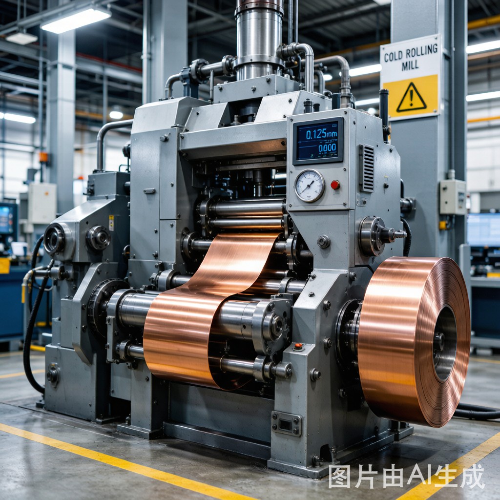
Understanding Cold Rolling Reduction in Copper Strip Production
Cold rolling is the backbone of precision copper strip manufacturing for SMT (Surface Mount Technology) lead frames. Unlike hot rolling, which operates above the metal’s recrystallization temperature, cold rolling deforms the copper at ambient conditions, producing tighter thickness tolerances, smoother surfaces, and enhanced mechanical properties critical for electronic component fabrication.
The reduction rate — defined as the percentage decrease in strip thickness per rolling pass — directly governs the final product’s dimensional accuracy, grain structure, and temper. For SMT lead frames that must meet tolerances of ±0.005 mm on 0.15–0.25 mm thick copper strip, understanding and optimizing reduction schedules is not optional; it is a manufacturing imperative.
What Is Reduction Rate?
The reduction rate (r) for a single pass is calculated as:
r = (t₀ − t₁) / t₀ × 100%
Where t₀ is the entry thickness and t₁ is the exit thickness. A typical multi-pass schedule for C19400 copper alloy transforming from 2.0 mm coil stock to 0.20 mm finished strip might involve 6–8 passes with per-pass reductions ranging from 15% to 40%.
Pass Schedule Design Strategies
Descending Reduction Schedule
The most common approach in precision copper strip rolling is a descending reduction schedule, where earlier passes carry heavier reductions (30–40%) and later passes apply lighter reductions (10–20%). This strategy offers several advantages:
- Heavy reductions in early passes break down coarse as-cast or hot-rolled grain structures more efficiently
- Lighter final passes allow the roll gap to be set with greater precision, achieving tighter gauge tolerance
- Reduced roll deflection and thermal expansion effects in light passes minimize thickness variation across the strip width
- Lower rolling forces in finishing passes reduce roll wear, maintaining surface quality (Ra ≤ 0.4 μm)
Ascending Reduction Schedule
Less common for SMT applications, ascending schedules start with light reductions and increase toward the end. This approach is sometimes used when initial coil flatness is poor and light “leveling” passes are needed before heavier reduction. However, it sacrifices final-pass gauge precision — a critical drawback for lead frame strip where ±0.005 mm tolerance is required.
Uniform Reduction Schedule
Some operations apply roughly equal reductions (e.g., 25% per pass) throughout the schedule. While simpler to set up, this approach does not optimize for either grain refinement (needs heavy early reduction) or gauge precision (needs light finishing reduction), making it suboptimal for SMT copper strip.
Gauge Control Systems for Thickness Precision
AGC (Automatic Gauge Control)
Modern cold rolling mills employ Automatic Gauge Control systems that continuously monitor exit thickness using X-ray or isotope gauges and adjust roll gap settings in real time. Key AGC parameters include:
- Monitor AGC: Corrects thickness deviations measured at the exit gauge point — response time 50–200 ms
- Feedforward AGC: Pre-adjusts roll gap based on entry thickness variations measured upstream — eliminates deviations before they form
- Mass Flow AGC: Combines entry and exit gauge data with strip speed to maintain constant volume flow, compensating for acceleration/deceleration transients
For SMT lead frame strip, mass flow AGC is preferred because it maintains thickness consistency during coil acceleration at the head end and deceleration at the tail end — regions where thickness variation is most common.
Roll Bending and Crown Compensation
Even with AGC, strip thickness varies across the width due to roll deflection under load. Roll bending systems (hydraulic cylinders applying counter-bending force to roll ends) and roll crowning (pre-shaped roll profiles) compensate for this deflection:
| Parameter | Effect on Strip Profile | Compensation Method |
|---|---|---|
| Roll deflection under load | Thicker center, thi
er edges |
Positive roll bending |
| Roll thermal crown | Thicker center (heat expansion) | Cooling spray zoning |
| Entry strip crown | Amplified thickness profile | Grinding target crown + bending |
| Asymmetric wear | One-sided thickness bias | Asymmetric bending |
Material-Specific Reduction Considerations
C11000 (ETP Copper) — Pure Copper
Pure copper exhibits excellent ductility and can tolerate per-pass reductions up to 50% without edge cracking. However, its low yield strength (≈70 MPa a
ealed) means rolling forces are moderate, and the material tends to work-soften at very high reductions due to dynamic recrystallization at room temperature in ultra-pure grades. This phenomenon requires careful monitoring — unexpected softening leads to gauge drift.
C19400 (Copper-Iron Alloy) — The SMT Lead Frame Standard
C19400 (Cu-2.35Fe-0.03P-0.1Zn) is the dominant alloy for SMT lead frames worldwide. Its higher yield strength (≈200 MPa half-hard) and fine Fe-dispersoid precipitation allow heavier reductions with less gauge variation. The alloy’s strengthening mechanism (precipitation hardening + work hardening) is synergistic with cold rolling — moderate reductions (20–35%) produce optimal temper combinations of strength and formability for progressive die stamping.
C19210 (Copper-Iron-Phosphorus)
Similar to C19400 but with slightly different Fe/P ratios, C19210 offers comparable rolling behavior. The key difference is its slightly lower tensile strength (≈320 MPa H04 temper vs ≈350 MPa for C19400), which translates to lower rolling forces and marginally better gauge control at ultra-thin gauges below 0.15 mm.
Intermediary A
ealing Decisions
Not all reduction schedules can run continuously from coil stock to finished gauge. When accumulated reduction exceeds approximately 85–90% (total across all passes), most copper alloys reach their work-hardening limit and require intermediary a
ealing to restore ductility.
When to A
eal
- Hardness threshold: When Vickers hardness exceeds the target temper’s upper limit (e.g., >130 HV for H02 temper C19400)
- Edge quality: When edge cracking or burr formation increases despite proper slitting parameters
- Springback control: When progressive die stamping shows excessive springback that ca
ot be compensated by tooling adjustments alone
- Formability limit: When the 180° bend test per ASTM E290 fails at the required radius
A
ealing Parameters for SMT Strip
| Alloy | Temperature Range | Atmosphere | Time | Resulting Grain Size |
|---|---|---|---|---|
| C11000 | 300–400°C | N₂/H₂ (4%) | 10–30 min | 15–30 μm (ASTM 7–8) |
| C19400 | 450–550°C | N₂/H₂ (4%) | 20–40 min | 10–20 μm (ASTM 8–9) |
| C19210 | 450–500°C | N₂/H₂ (4%) | 15–30 min | 8–15 μm (ASTM 9–10) |
Fine grain sizes are essential for SMT lead frames because they provide uniform mechanical properties across the strip, consistent etching behavior in chemical milling, and predictable springback in bending/forming operations.
Thickness Measurement and Quality Control
In-Process Gauge Monitoring
Thickness is measured at multiple points in the rolling process:
- Entry gauge: Contact micrometer or non-contact laser — provides feedforward data for AGC
- Exit gauge: X-ray or isotope thickness gauge — primary monitor for AGC feedback loop
- Post-rolling inspection: Contact micrometer sampling at 50 mm intervals across strip width — verifies cross-profile uniformity
Tolerance Standards for SMT Lead Frame Strip
| Nominal Thickness | Standard Tolerance | Precision Tolerance |
|---|---|---|
| 0.10 mm | ±0.008 mm | ±0.003 mm |
| 0.15 mm | ±0.010 mm | ±0.005 mm |
| 0.20 mm | ±0.012 mm | ±0.005 mm |
| 0.25 mm | ±0.015 mm | ±0.006 mm |
| 0.30 mm | ±0.018 mm | ±0.008 mm |
Precision tolerances are achievable only with AGC-equipped mills, proper roll bending compensation, and controlled rolling speeds (typically 100–300 m/min for finishing passes).
Practical Recommendations for SMT Copper Strip Buyers
When sourcing copper strip for SMT lead frame production, consider these reduction-related quality factors:
- Request pass schedule documentation: Suppliers who provide rolling pass records demonstrate process transparency and allow traceability for thickness variation root cause analysis
- Specify grain size requirements: ASTM grain size number 8 or finer ensures uniform stamping behavior — this is achievable only with properly designed reduction + a
ealing schedules
- Verify gauge uniformity across the coil: Request gauge reports showing thickness at head, middle, and tail sections, plus cross-profile data at 5 positions across the width
- Match temper to stamping complexity: H02 (quarter-hard) for simple bends; H04 (half-hard) for complex progressive die operations with multiple forming stations
- Consider Southeast Asian climate effects: High humidity environments can accelerate surface oxidation on bare copper strip — request anti-tarnish packaging for coils stored longer than 2 weeks
Conclusion
Cold rolling reduction rate is far more than a process parameter — it is the primary determinant of copper strip quality for SMT lead frame manufacturing. Descending reduction schedules, combined with modern AGC systems and appropriate intermediary a
ealing, produce the tight-gauge, fine-grain, consistent-temper strip that electronics manufacturing demands. Understanding these principles helps SMT component buyers evaluate supplier capability and ensures that the copper strip entering your stamping line will perform predictably from first article to full production.



