Introduction
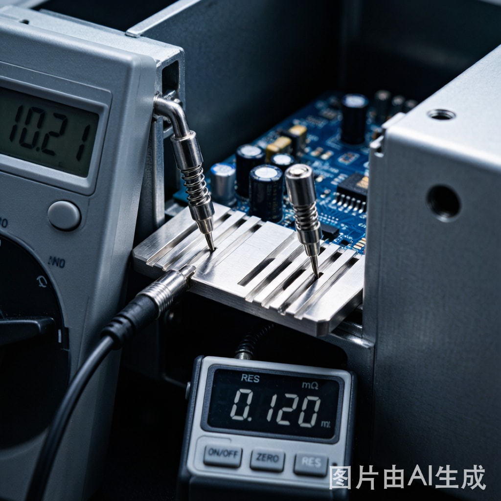
The shielding effectiveness of an EMI gasket is only as good as the electrical contact it makes with the mating enclosure surfaces. A gasket with excellent material conductivity can still fail to provide adequate shielding if the contact resistance at the gasket-to-enclosure interface is excessive. Quantifying this contact resistance — and doing so repeatably — is essential for quality assurance, supplier qualification, and design validation. This article examines the measurement methods, standards, and best practices for characterizing EMI gasket contact resistance.
Why Contact Resistance Matters
Contact resistance at the gasket-enclosure interface directly impacts shielding effectiveness through transfer impedance (Zt). For a gasket with bulk resistance Rb and contact resistance Rc at each interface, the total DC resistance across the gasketed joint is:
Rtotal = Rb + 2 × Rc
In practice, Rc often dominates. A BeCu fingerstock gasket with bulk resistance of 2 mΩ can exhibit a total joint resistance of 10-50 mΩ if the contact interfaces are compromised by oxidation, insufficient compression, or surface contamination. At 1 GHz, where skin depth in copper is approximately 2 µm, even nanometer-scale oxide layers can increase the RF impedance of the joint by an order of magnitude.
DC Four-Wire Kelvin Measurement
The four-wire Kelvin method is the gold standard for low-resistance measurements and is specified in MIL-DTL-83528 (General Specification for EMI/RFI Shielding Gaskets). The technique separates current-carrying leads from voltage-sensing leads, eliminating lead and probe contact resistance from the measurement:
- Current injection: A known DC current (typically 100 mA to 1 A) is passed through the gasket assembly via two outer leads. The current level must be high enough to produce a measurable voltage drop but low enough to avoid self-heating effects that would change the contact resistance.
- Voltage sensing: Two separate i
er leads measure the voltage drop across the gasket-to-panel interface. Because the voltmeter presents a very high input impedance (>10 MΩ), negligible current flows through the sense leads, eliminating their resistance from the measurement.
- Calculation: Contact resistance is calculated using Ohm’s law: R = V/I, where V is the measured voltage across the contact interface and I is the injected current.
Test Fixture Design Requirements
Fixturing is critical to measurement repeatability. Key design considerations include:
- Electrode material: Test electrodes should replicate the actual enclosure material. Aluminum 6061-T6 (conductive), chromate conversion-coated aluminum, and nickel-plated aluminum are common choices. Different electrode surface finishes can produce contact resistance variations of 2-5×, making it essential to test with the intended enclosure material.
- Surface finish: Electrode surfaces should be specified with the same roughness (Ra) and flatness as the production enclosure. MIL-DTL-83528 recommends Ra ≤ 1.6 µm for test electrodes.
- Compression control: A calibrated force application mechanism — typically a pneumatic cylinder with a precision regulator or a motorized lead screw with a load cell — must apply a known, repeatable compression force. The standard test compression is typically 50-75% of the gasket’s rated working compression range.
- Fixture resistance baseline: A “short” measurement — co
ecting the electrodes directly without a gasket — establishes the fixture baseline resistance, which should be <0.1 mΩ for meaningful measurements.
Industry Standards and Acceptance Criteria
Several standards govern EMI gasket contact resistance testing:
- MIL-DTL-83528: The primary standard for military EMI gasket qualification. Specifies that initial contact resistance shall not exceed 5 mΩ per contact interface for fingerstock gaskets and 10 mΩ for conductive elastomer gaskets. After environmental exposure (thermal cycling, humidity, salt spray), contact resistance shall not increase by more than 100%.
- SAE ARP-1705: Aerospace-industry standard that defines a coaxial test fixture method for measuring transfer impedance of gasket materials from 10 kHz to 1 GHz. Transfer impedance below 10 mΩ·m is typically required for aerospace applications.
- IEC 61523-3: Defines transfer impedance measurement for gasketed joints using the line injection method. Particularly relevant for European automotive and industrial applications.
Transfer Impedance: The RF Perspective
While DC contact resistance measurements are practical and widely used for production quality control, they do not fully capture RF behavior. At frequencies above 100 MHz, transfer impedance (Zt) — the ratio of voltage induced on the “quiet” side of a shielded enclosure to the current flowing on the “noisy” side — provides a more complete picture of gasket performance.
Transfer impedance is measured using a coaxial or triaxial test fixture. For fingerstock gaskets with good contact integrity, Zt values below 1 mΩ·m at 1 GHz are achievable. Degraded contact interfaces with 10-20 mΩ DC resistance typically exhibit Zt of 5-20 mΩ·m at GHz frequencies, corresponding to a 20-30 dB reduction in shielding effectiveness below the theoretical maximum.
Production Testing Strategy
Full transfer impedance measurement is impractical for production lot testing due to fixture complexity and measurement time (typically 15-30 minutes per sample). A practical production strategy combines:
- DC contact resistance (100% visual + sample test): A rapid (<30 seconds) four-wire measurement at the defined compression level. Pass/fail limits are established based on correlation to transfer impedance limits established during qualification.
- Compression force verification (each assembly): Rather than measuring resistance on every gasket, verifying that the applied compression force is within specification ensures the design contact resistance is achieved.
- Periodic transfer impedance audit (per lot / per shift): One full transfer impedance measurement per manufacturing lot validates that DC measurements remain correlated to RF performance.
Conclusion
Accurate contact resistance measurement is the foundation of EMI gasket quality assurance. The four-wire Kelvin method, properly fixtured and correlated to RF transfer impedance measurements, provides a practical and reliable framework for both design validation and production quality control. By establishing clear pass/fail criteria based on application requirements and verifying measurement repeatability through careful fixture design, manufacturers can ensure consistent shielding performance across production volumes. For high-frequency applications above 1 GHz, supplementing DC measurements with periodic transfer impedance audits closes the gap between simple resistance testing and real-world RF shielding behavior.



