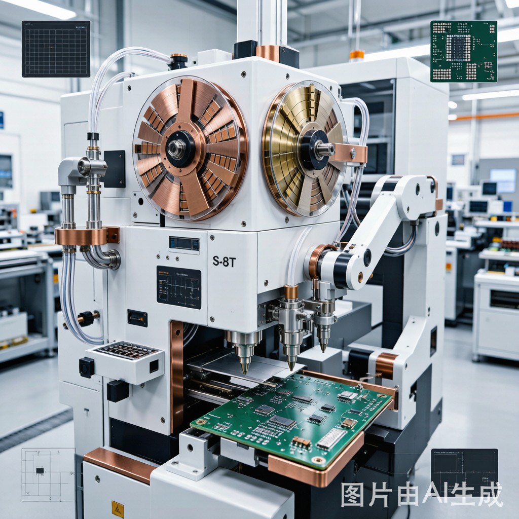
Introduction
Modern SMT assembly lines place thousands of components per hour with accuracy measured in micrometers. Behind this speed lies a careful calibration process that ensures each feeder delivers parts to the exact pick location expected by the placement machine. When feeders drift out of calibration, components land off-pad, rotated, or missing entirely. For heavy copper and brass components, which are denser and more irregular than standard passive parts, feeder calibration becomes even more critical.
How Tape Feeders Work
Tape feeders are the most common mechanism for presenting small surface-mount components to a pick-and-place machine. Components sit in pockets formed in embossed carrier tape, covered by a top cover tape. A sprocket engages indexing holes along the tape edge and advances the tape by one pocket per cycle. The placement head then picks the component from the exposed pocket using a vacuum nozzle.
Accurate placement depends on the relationship between the tape pocket position, the feeder pick point stored in the machine program, and the actual nozzle tip location. Any mismatch causes a placement offset. Because copper and brass components are heavier than ceramic or plastic parts, they also require stronger vacuum and more precise nozzle selection to prevent drops or shifts during transport.
Calibration Procedures
Feeder calibration begins with mechanical alignment. The feeder must sit firmly in its slot with no lateral play. The tape path should be straight, and the cover tape peeling mechanism should expose each pocket cleanly without lifting the component. Worn sprockets, damaged tape guides, or weak cover tape peeling force are common causes of inconsistent indexing.
Pick-point calibration uses the machine vision system or a manual teach function to record the exact coordinates where the nozzle should descend. Most modern machines can automatically measure the pickup offset by picking a part and inspecting it under the upward-looking camera. This offset is then stored and applied to all subsequent placements from that feeder.
Key Calibration Parameters
| Parameter | Typical Tolerance | Effect If Out of Spec |
|---|---|---|
| Pick-Point X-Y | ± 0.05 mm | Offset placement, solder bridging |
| Component Height | ± 0.10 mm | Poor placement pressure, cracked parts |
| Nozzle Vacuum | Per supplier spec | Dropped or shifted components |
| Tape Indexing | ± 0.10 mm | Missed picks, rotated parts |
| Cover Tape Peel Force | 10 – 60 g | Component lift or tape jams |
Vision Alignment and Component Recognition
After picking, components are carried to a downward-looking or upward-looking camera for inspection. The vision system measures the component position relative to the nozzle center, detects rotation, and verifies that the correct part was picked. This information is used to correct the placement coordinates in real time.
Copper and brass components can challenge vision systems because their reflective surfaces create glare and their irregular shapes may not match standard package libraries. Proper lighting, contrast settings, and custom component models are often necessary. For leaded or formed copper parts, the vision system must recognize the component body and lead tips separately to place them accurately on the PCB pads.
Handling Heavy Copper and Brass Parts
Copper strip and brass components are significantly denser than typical SMT passives. A small brass co
ector may weigh several times more than a ceramic capacitor of the same footprint. This mass affects pickup reliability, nozzle wear, and placement force calibration. Heavier parts require larger nozzles, higher vacuum, and slower placement speeds to prevent component shift or bouncing.
Oxidation on bare copper parts can also reduce vacuum seal quality. Storing copper components in dry, sealed packaging and using them within their shelf life helps maintain consistent pickup. For large brass shielding cans or co
ector bodies, tray feeders or direct substrate feeding may be more reliable than tape feeders because they reduce handling and allow more stable presentation.
Preventing Common Placement Defects
Many placement defects trace back to feeder or program issues rather than machine mechanics. Tombstoning of small passive components often results from uneven paste deposition, but it can also be caused by part rotation or off-center placement. Skewed co
ectors and lead-frame components usually indicate a pick-point offset or incorrect nozzle size.
A preventive maintenance schedule is the best defense. Feeders should be cleaned, inspected, and recalibrated on a defined interval or after any crash. First-article inspection using a high-resolution measurement system catches placement drift before it affects a full production lot. Statistical process control of placement accuracy data helps identify feeders that are approaching their maintenance threshold.
Conclusion
SMT feeder calibration and placement accuracy are foundational to mixed copper component assembly. The weight, reflectivity, and irregular geometry of copper and brass parts place extra demands on feeder setup, nozzle selection, and vision programming. By following disciplined calibration procedures and monitoring placement data, manufacturers can achieve the high yields and reliable solder joints required in today’s dense electronic assemblies.



