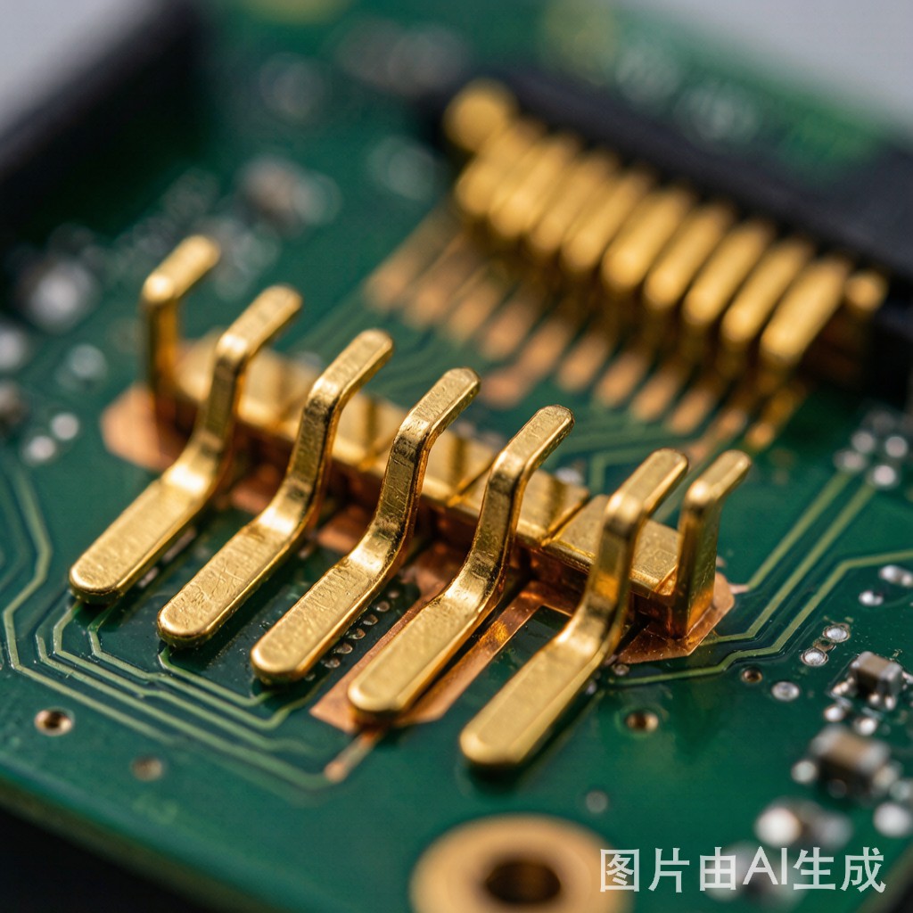
The Gold Plating Decision for SMT Card-Edge Co
ectors
Card-edge co
ectors—those gold-plated contact fingers on the edge of a PCB that mate with corresponding socket contacts—require plating that simultaneously serves three demanding functions: low and stable contact resistance over thousands of insertion cycles, corrosion resistance in potentially harsh operating environments, and compatibility with the SMT reflow process that attaches components to the same board. The gold plating specification directly determines whether a card-edge co
ector will maintain reliable electrical contact through its design life or develop intermittent co
ections from wear and corrosion.
Two gold plating technologies dominate card-edge co
ector manufacturing: hard electrolytic gold (often called “hard gold” or Type II gold per ASTM B488) and electroless nickel immersion gold (ENIG, Type III per IPC-4552). While both deliver a gold contact surface over nickel barrier on copper, their fundamentally different deposition methods produce gold layers with dramatically different properties—particularly hardness, wear resistance, thickness, and cost.
Selecting the wrong gold plating for a card-edge application leads to predictable failures: co
ector fingers that wear through the gold layer after 50 insertion cycles instead of 500, gold wire bond pads that refuse to solder properly after SMT reflow diffusion, or excessive gold cost in non-wearing applications where a thi
er immersion layer would suffice.
## Hard Electrolytic Gold: The Wear-Resistant Standard
### Electrodeposition Process
Hard electrolytic gold plating deposits gold onto the PCB surface through electrochemical reduction in an acidic gold cyanide bath. The PCB edge co
ector fingers serve as the cathode; a gold anode or inert anode (platinum-coated titanium) supplies gold ions. Direct current drives Au⁺ ions from solution onto the copper-nickel surface, building a gold layer with precisely controlled thickness.
The “hard” designation comes from alloying elements—typically 0.1-0.3% cobalt, nickel, or iron—co-deposited with the gold to refine grain structure and increase hardness. These alloying elements create a gold layer with hardness of 130-200 Knoop (HK₂₅), compared to 60-90 HK₂₅ for pure soft gold.
Key process characteristics:
– Current density: 5-15 ASD (A/dm²), controlling deposition rate and grain structure
– Plating thickness: 0.75-2.5 μm (30-100 μin) gold over 2.5-5.0 μm (100-200 μin) nickel barrier
– Selective plating: Edge fingers plated through controlled immersion depth, masking, or brush plating—remaining PCB surface not plated
– Post-plate bake: 150°C for 1-2 hours to drive off hydrogen and relieve plating stress
### Hard Gold Properties and Performance
| Property | Hard Electrolytic Gold | Significance for Card-Edge |
|—|—|—|
| Hardness (HK₂₅) | 130-200 | High wear resistance; withstands 500-10,000+ insertion cycles |
| Gold thickness | 0.75-2.5 μm | Thick layer provides wear margin; lasts through design life |
| Nickel thickness | 2.5-5.0 μm | Diffusion barrier prevents Cu-Ni-Au interdiffusion |
| Porosity | Low (dense electrodeposited layer) | Minimal corrosion path to nickel underlayer |
| Contact resistance | 1-5 mΩ (initial) | Excellent—low and stable |
| Ductility | 1-3% elongation | Low (hard) but sufficient for co
ector flex |
| Wear resistance (Taber) | Excellent | Withstands mechanical abrasion from socket contact wiping |
### Hard Gold Advantages for Card-Edge Applications
Hard gold’s primary advantage is wear resistance. The cobalt/nickel-alloyed grain structure provides a hard, durable surface that withstands repeated insertion/withdrawal cycles without wearing through to the nickel underlayer. For high-cycle applications—test equipment, backplane co
ectors, server blade slots, industrial control card cages—hard gold is essentially mandatory.
Additional advantages include:
– Controlled thickness: Electrolytic deposition allows precise thickness control, ensuring adequate gold coverage for the required insertion cycle life
– Low porosity: Dense electrodeposited structure minimizes pores that would expose the nickel underlayer to corrosion
– Proven reliability: Decades of telecom and mil-aero field data confirm hard gold’s long-term stability in card-edge applications
### Hard Gold Limitations
– Process complexity: Requires electrical co
ection to each finger during plating (plating bus), which must be removed after plating—adding fabrication steps
– Solderability concern: Cobalt/nickel-alloyed hard gold solders less readily than pure gold; soldering directly to hard gold can produce embrittled joints from gold-tin intermetallic formation
– Higher cost: Thicker gold layer (0.75-2.5 μm vs 0.05-0.12 μm for ENIG) means 10-20x more gold per co
ector
– Plating bus removal: The plating bus co
ects all fingers during electrolytic deposition but must be removed (routed/milled) after plating, consuming PCB real estate at the board edge
## ENIG: Immersion Gold on Card-Edge Contacts
### Electroless Deposition Process
ENIG deposits gold through an immersion (displacement) reaction rather than electrolysis. The process sequence on copper pads is:
1. Microetch: Clean and micro-roughen copper surface
2. Catalyst/activation: Palladium catalyst deposited on copper surface
3. Electroless nickel: Nickel-phosphorus alloy (typically 7-10% P) deposited through autocatalytic chemical reduction—no electrical current required; thickness 3-6 μm
4. Immersion gold: Gold deposited through galvanic displacement—gold ions in solution replace nickel atoms at the surface; thickness self-limiting at 0.05-0.12 μm (2-5 μin) as the gold layer blocks further nickel dissolution
The immersion mechanism is fundamentally different from electrolytic deposition: it is a self-limiting surface reaction, not an externally driven electrochemical process. This produces a very thin, pure gold layer (Type III, 99.9% Au) with no alloying elements.
### ENIG Properties and Performance
| Property | ENIG | Significance for Card-Edge |
|—|—|—|
| Hardness (HK₂₅) | 60-90 (pure Au) | Low—wears through in 50-100 insertion cycles |
| Gold thickness | 0.05-0.12 μm | Very thin—minimal wear margin |
| Nickel thickness | 3-6 μm | Adequate diffusion barrier |
| Porosity | Moderate (thin layer pores) | Corrosion path exists, especially for thin gold over rough nickel |
| Contact resistance | 1-3 mΩ (initial) | Excellent initially but degrades as gold wears |
| Solderability | Excellent | Pure gold wets readily with SAC305 and SnPb |
| Wire bondability | Good | Suitable for aluminum and gold wire bonding |
| Process simplicity | High | No plating bus, no electrical co
ections required |
### ENIG Advantages
– Solderability: Pure immersion gold provides excellent solder wetting—far better than hard gold for soldered co
ections
– Planarity: Uniform thickness across the entire PCB surface—critical for fine-pitch SMT pads where coplanarity matters
– Wire bondability: Suitable for gold and aluminum wire bonding on the same board as SMT components
– Process simplicity: No plating bus, no selective deposition, no post-plating bus removal—the entire board is plated uniformly
– Lower cost: Very thin gold layer means minimal gold consumption; the cost driver is the nickel process, not gold
### ENIG Card-Edge Limitations
ENIG’s primary limitation for card-edge applications is wear life. The 0.05-0.12 μm gold layer provides minimal wear margin:
| Insertion Cycles | ENIG Condition | Hard Gold Condition |
|—|—|—|
| 0 (as-plated) | Gold surface intact, <5 mΩ | Gold surface intact, <5 mΩ |
| 25-50 | Gold worn at contact point, nickel exposed | Gold surface intact |
| 50-100 | Nickel oxide formation, 10-50 mΩ | Gold surface intact, <5 mΩ |
| 100-200 | Contact resistance erratic, corrosion visible | Gold thi
ing, 5-10 mΩ |
| 500+ | Co
ector failure probable | Gold still present, <15 mΩ |
| 2000+ | Failed | Gold thi
ing, may reach nickel |
| 10,000+ | Failed | Gold wear margin exhausted, nickel contact |
ENIG is suitable only for low-cycle card-edge applications (1-10 insertions: configuration jumpers, one-time assembly co
ectors, field-replaceable units where replacement occurs once in product life).
## Selection Decision Framework
### By Insertion Cycle Requirement
| Application | Expected Cycles | Recommended Plating |
|—|—|—|
| Server blade edge co
ector | 100-500 | Hard gold (1.25-2.0 μm) |
| Telecom line card | 50-200 | Hard gold (0.75-1.5 μm) |
| Industrial control card | 200-1000 | Hard gold (1.5-2.5 μm) |
| Test equipment interface | 500-5000 | Hard gold (2.0-2.5 μm) |
| Consumer electronics card | 5-20 | ENIG (0.05-0.12 μm) |
| Configuration jumper board | 1-5 | ENIG (0.05-0.12 μm) |
| One-time assembly co
ector | 1-3 | ENIG (0.05-0.12 μm) |
| Automotive ECU card edge | 10-50 | Hard gold (0.75-1.25 μm) |
### By Environmental Severity
| Environment | ENIG Suitability | Hard Gold Suitability |
|—|—|—|
| Office/indoor (25°C, 50% RH) | Good for low cycle | Excellent for all cycles |
| Industrial (40°C, 80% RH, mild corrosive gases) | Marginal—corrosion accelerates wear | Excellent—thick gold resists |
| Automotive under-hood (85°C+, vibration) | Not recommended | Required—thermal cycling + vibration accelerates wear |
| Outdoor/telecom (-40 to +85°C, condensing humidity) | Not recommended | Required—condensation + thermal cycling |
| Clean room/controlled | Acceptable for low cycle | Excellent |
### Cost Comparison
| Cost Factor | ENIG | Hard Gold (selective) |
|—|—|—|
| Gold consumption | 0.05-0.12 μm × area | 0.75-2.5 μm × co
ector area only |
| Processing cost | Low (full panel immersion) | Medium-High (selective + bus removal) |
| Gold cost per co
ector finger | $0.001-0.003 | $0.01-0.05 |
| Total PCB cost adder | 10-15% over bare copper | 15-30% over bare copper (varies with co
ector count) |
| Rework cost (gold-related) | Low (rare) | Low (rare—hard gold failures usually wear, not process defects) |
## Design Rules for Gold-Plated Card-Edge Co
ectors
### Plating Bus Design (Hard Gold Only)
The plating bus co
ecting all edge fingers for electrolytic deposition should:
– Co
ect to the board edge at a location where routing removal is feasible (usually the board perimeter, removed during final routing)
– Be at least 0.5 mm wide to carry plating current without excessive voltage drop
– Locate the bus outside the final board outline by adding 2-3 mm to the panel border
### Nickel Barrier Thickness
Both hard gold and ENIG require a nickel barrier between gold and copper to prevent copper diffusion through the gold layer (which forms non-conductive copper oxide at the surface). Minimum nickel thickness: 2.5 μm for hard gold, 3 μm for ENIG per IPC-4552.
### Gold Thickness Specification
Specify gold thickness per application requirements, not arbitrary standards:
– Hard gold for card-edge: 0.75-2.5 μm depending on insertion cycles
– ENIG for soldered pads only (not card-edge): 0.05-0.12 μm per IPC-4552 Class 2/3
– Never specify thicker gold than needed—excess gold cost is pure waste
## Conclusion: Match Plating to Application Requirements
The choice between hard electrolytic gold and ENIG for SMT card-edge co
ectors is straightforward when analyzed against insertion cycle life: if the co
ector will be mated more than 20-30 times in its service life, hard gold is required. ENIG’s sub-0.12 μm gold layer simply lacks the thickness to withstand mechanical wear from repeated contact wiping.
For consumer electronics card-edge co
ectors with 1-10 insertion cycles, ENIG provides adequate performance at significantly lower cost. For all industrial, automotive, telecom, and high-reliability applications with co
ector cycling requirements, hard electrolytic gold remains the proven standard. The cost premium for hard gold—$0.01-0.05 per co
ector finger—is negligible compared to the cost of a field failure from worn-through gold causing intermittent contact in a deployed product.



