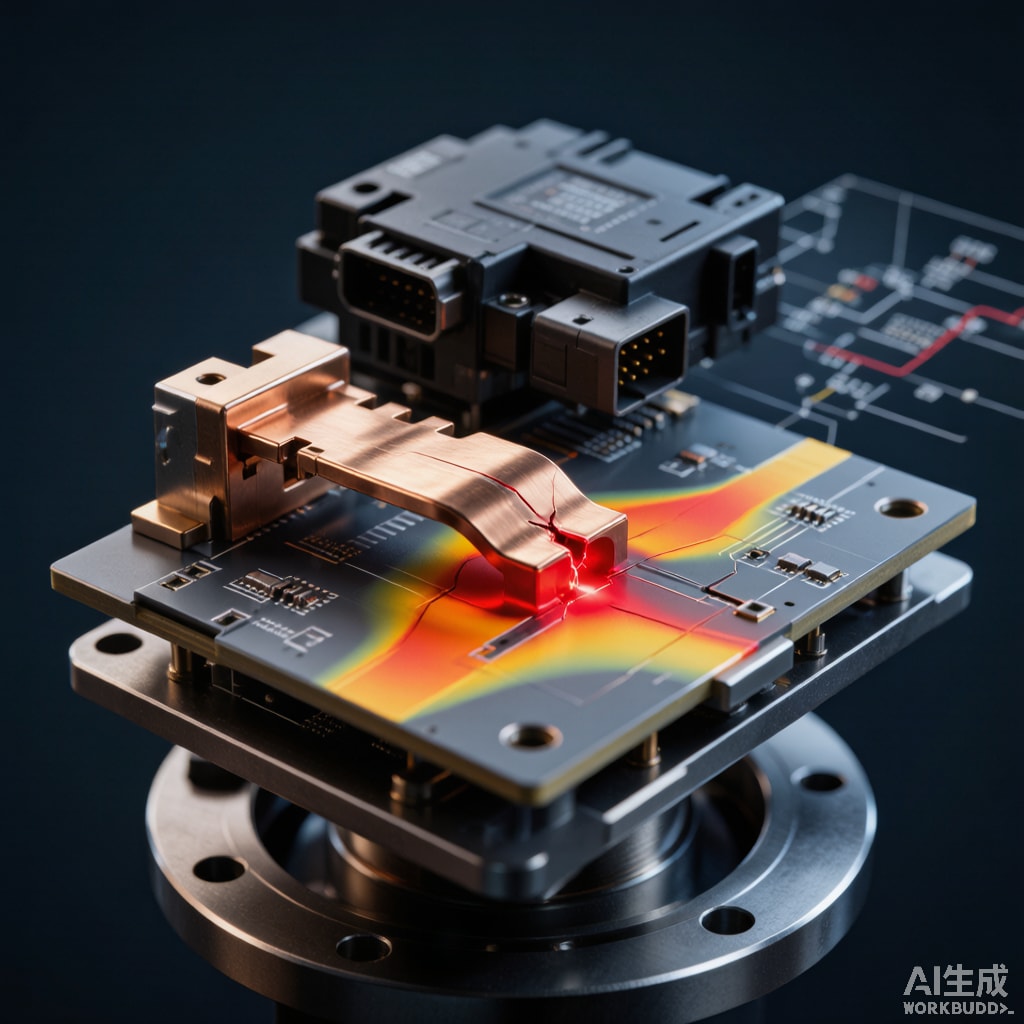
Introduction: Why Vibration Fatigue Matters in Automotive SMT Lead Frames
Modern automotive electronics operate in one of the most demanding mechanical environments of any consumer product. Engine control units, transmission controllers, battery management systems and ADAS sensor modules are mounted directly to engines, transmissions or chassis structures, where they must survive continuous random vibration from 5 Hz to 2000 Hz at amplitudes up to 30 g RMS for the entire 8–15 year vehicle service life. The SMT copper strip lead frame inside these packages is often the first link that fails when the package cracks or the chip interco
ect fatigues, so designing for vibration fatigue is a critical reliability requirement rather than an academic exercise.
Unlike thermal fatigue, vibration fatigue is dominated by the elastic-plastic bending strain imposed at each resonant frequency of the package. The Manson-Coffin strain-life relationship and the Basquin high-cycle relationship together govern how many cycles a copper strip can survive at a given strain amplitude. This article explains the underlying mechanics, shows how to apply them to SMT lead frames, and discusses alloy and thickness selection for Southeast Asian automotive electronics manufacturing.
Strain-Life and Stress-Life Approaches
The Manson-Coffin Strain-Life Equation
For low-to-medium cycle fatigue (10² to 10⁵ cycles), the fatigue life is dominated by plastic strain amplitude. The Manson-Coffin relationship expresses total strain amplitude as the sum of elastic and plastic components:
Δε/2 = (σ′f/E)(2N)b + ε′f(2N)c
where σ′f is the fatigue strength coefficient, E is Young’s modulus, b is the fatigue strength exponent, ε′f is the fatigue ductility coefficient, c is the fatigue ductility exponent, and N is cycles to failure. Typical copper alloy parameters:
| Alloy | E (GPa) | σ′f (MPa) | b | ε′f | c |
|---|---|---|---|---|---|
| C11000 ETP (a
ealed) |
110 | 180 | -0.10 | 0.30 | -0.55 |
| C19400 Cu-Fe-P | 120 | 520 | -0.08 | 0.18 | -0.62 |
| C70250 Cu-Ni-Si | 130 | 750 | -0.09 | 0.05 | -0.70 |
At strain amplitudes between 0.001 and 0.01, a
ealed C11000 typically gives 10³ to 10⁴ cycles to crack initiation, while C70250 can deliver 10⁵ to 10⁶ cycles under the same strain. The practical implication: high-strength copper alloys substantially extend lead frame vibration life at the cost of lower electrical conductivity.
Basquin High-Cycle Regime
For high-cycle fatigue above 10⁵ cycles, the elastic strain dominates. The Basquin relationship reads:
σa = σ′f(2N)b
For SMT lead frames operating at typical vibration amplitudes of 50–500 microstrain, fatigue life is usually in the 10⁶ to 10⁸ cycle range — well within the high-cycle regime. The fatigue limit (endurance limit) of copper alloys is often taken at 10⁷ cycles, but this value depends strongly on mean stress.
Mean Stress Correction
Automotive packages see vibration superimposed on a static bending stress from thermal mismatch or board flexure. The Goodman, Gerber or SWT (Smith-Watson-Topper) relationships correct for this mean stress effect:
- Goodman: σa/σ′f + σm/σu = 1 (conservative, simple)
- Gerber: (σa/σ′f) + (σm/σu)² = 1 (better fit for ductile alloys)
- SWT: σmax·εa·E = (σ′f)²(2N)2b + σ′f·ε′f·E·(2N)b+c (best for non-proportional loading)
For copper lead frames with thermal mean stresses of 30–80 MPa, the Goodman correction typically reduces allowable alternating stress by 25–40%.
Automotive Vibration Profiles: ISO 16750 and Customer Specifications
ISO 16750-3 Test Profiles
ISO 16750-3 defines the mechanical vibration tests for automotive electronic modules. The most demanding profile is “random vibration with temperature” (test VII), with the following typical PSD envelope:
| Frequency (Hz) | PSD (g²/Hz) |
|---|---|
| 5 | 0.0125 |
| 10 | 0.06 |
| 20 | 0.12 |
| 40 | 0.12 |
| 80 | 0.06 |
| Overall RMS | ~3.5 g |
This profile represents chassis-mounted components. For engine-mounted modules, ISO 16750-3 profile IX specifies 18 g RMS with peak accelerations up to 60 g. Components mounted directly to the powertrain must survive an even harsher 30 g RMS profile.
Customer-Specific Profiles
Most OEMs supplement ISO 16750 with additional profiles. Volkswagen PV 1208, Toyota TSC7001G and GM GMW3172 all use random vibration profiles with higher RMS levels and extended low-frequency content to capture engine harmonics. The cumulative damage from these profiles is summed with Miner’s rule:
D = Σ (ni/Ni)
where ni is cycles at stress level i and Ni is fatigue life at that level. Failure occurs when D ≥ 1. A well-designed lead frame holds D below 0.3 over the 8-year vehicle service life.
Alloy and Thickness Selection for Vibration Resistance
Pure vs Age-Hardened Copper
A
ealed C11000 has the highest conductivity but the lowest fatigue strength. C19400 (Cu-Fe-P) and C70250 (Cu-Ni-Si) deliver 2–4× longer fatigue life through precipitation strengthening, at the cost of 30–50% lower electrical conductivity. The trade-off matrix for a vibration-prone lead frame:
| Alloy | Conductivity (% IACS) | Fatigue Life Factor | Best Application |
|---|---|---|---|
| C11000 a
ealed |
101 | 1.0 (baseline) | Static load, non-vibration |
| C19400 H04 | 65 | 2.5× | Body controller, mid-stress |
| C70250 TM04 | 50 | 4.0× | Engine ECU, high-stress |
| C17200 Be-Cu (TB00) | 22 | 3.0× | Sensor lead frames, contact springs |
Strip Thickness Optimization
Increasing copper strip thickness from 0.10 mm to 0.25 mm raises section stiffness by 2.5× in the thickness³ sense, reducing vibrational strain amplitude in the lead frame. Doubling thickness typically reduces peak strain by 30–40%, extending fatigue life by roughly an order of magnitude. The trade-off is increased package weight, larger package size and higher cost per part. For vibration-prone automotive modules, 0.20–0.30 mm thickness is standard.
Notch and Bend Radius Effects
Stress concentrations at the i
er bend radius of stamped lead frames are the usual crack initiation site. A bend radius of 0.2 mm (typical for fine-pitch lead frames) creates a stress concentration factor Kt of 1.8–2.2, reducing fatigue life by 30–60% compared to a smooth bend. Increasing the bend radius to 0.4 mm or specifying a localized stress-relief a
eal after stamping can substantially extend life.
Accelerated Vibration Test Design
Test Boards and Fixtures
Accelerated vibration tests use simplified PCB boards mounted to electrodynamic shakers. The board fixture must replicate the package’s first natural frequency and mode shape, since the package sees amplified strain at resonance. Calibration with strain gauges on representative lead frames is essential. Typical test durations are 8 hours per axis at 3 g RMS, equivalent to roughly 1000 km of road load.
Failure Analysis Workflow
When lead frames fail in test, a systematic workflow isolates the root cause:
- Visual and SEM inspection of the fracture surface to identify crack initiation (striation spacing, beach marks)
- Cross-section metallography to check grain structure, inclusions and any residual stress concentration
- FEA modal and harmonic analysis to compare predicted strain hot spots with observed crack locations
- Iterative design changes — bend radius, strip thickness, alloy temper — followed by re-test
Manufacturing Process Impact on Fatigue Life
Stamping-Induced Work Hardening
Progressive die stamping work-hardens the bend regions of a copper strip lead frame, raising local hardness by 30–50% and introducing residual tensile stress on the outer bend radius. A post-stamp stress-relief a
eal at 250–350°C for 30–60 minutes restores ductility and reduces residual stress, but partial recrystallization may also reduce dimensional accuracy.
Plating-Induced Hydrogen Embrittlement
Tin, tin-lead or nickel plating introduces hydrogen during the plating process. Hydrogen absorption reduces ductility and can dramatically shorten fatigue life, particularly in high-strength alloys. A 200°C × 4 hour post-plate bake eliminates mobile hydrogen and should be specified for vibration-prone automotive components.
Conclusion
SMT copper strip lead frame vibration fatigue is a reliability engineering discipline combining strain-life mechanics, automotive vibration profiles, alloy selection and process optimization. By choosing high-strength alloys such as C19400 or C70250, optimizing strip thickness and bend radii, controlling stamping residual stress and validating with ISO 16750-style testing, Southeast Asian automotive electronics manufacturers can deliver lead frames that survive 8–15 years of powertrain service without vibration-induced failure. The investment in materials and process control pays back through warranty cost reduction and improved customer confidence.



