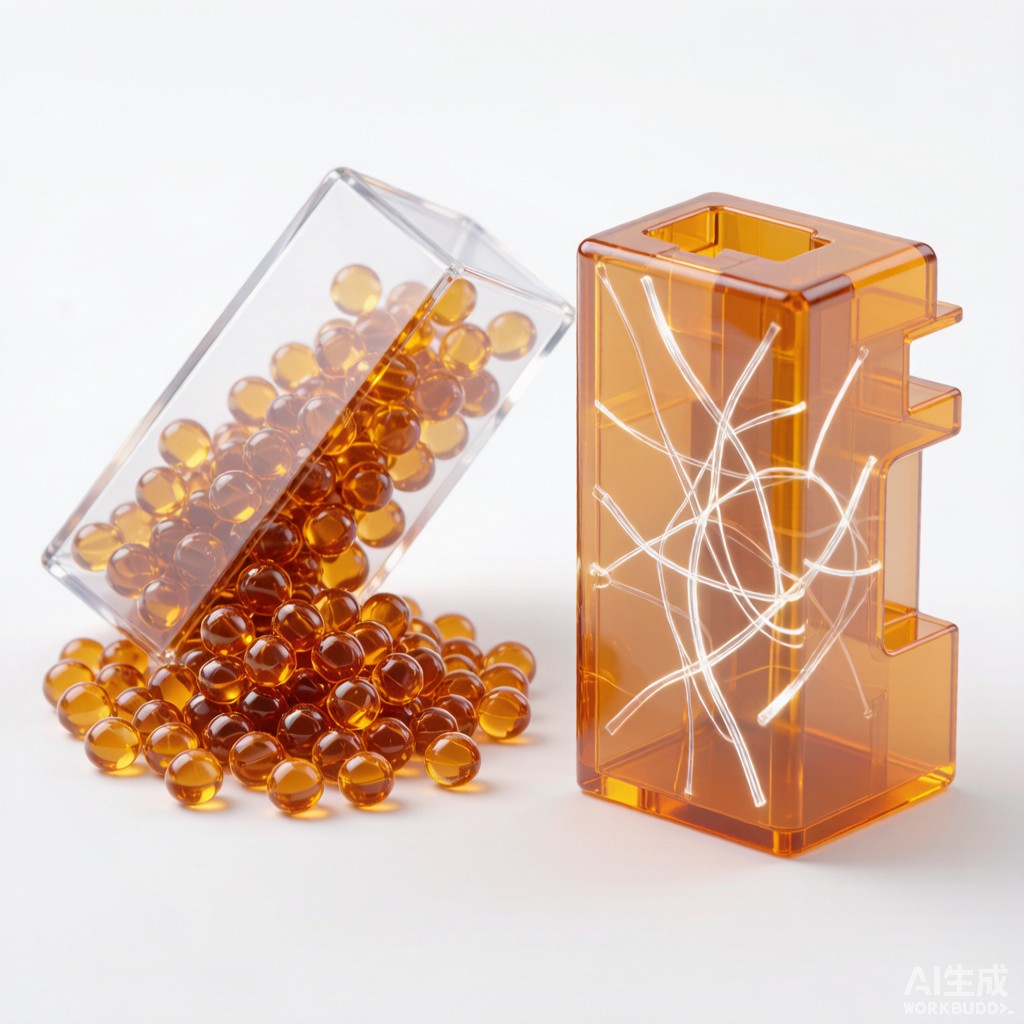
Introduction: Plastics That Survive Reflow
Modern surface-mount co
ectors, relay sockets, sensor housings and LED holders must survive lead-free solder reflow peaks of 245-260°C without warping, discoloring or losing dimensional accuracy. Standard engineering plastics such as ABS, PA66 or unreinforced PBT ca
ot tolerate these temperatures. Instead, electronics manufacturers turn to high-performance thermoplastics, among which polyphenylene sulfide (PPS) modified with glass fiber is one of the most cost-effective and widely used options.
This article explains the properties, processing and application of glass-filled PPS modified plastic pellets for SMT co
ector housings and other reflow-stable electronic components.
Why PPS for SMT Components
Thermal and Chemical Stability
PPS is a semi-crystalline aromatic polymer with a high melting point of approximately 285°C and a heat deflection temperature above 260°C. Unlike aliphatic polyamides, PPS absorbs very little moisture — typically less than 0.05% — which eliminates the need for pre-drying in many applications and reduces dimensional changes in humid environments. PPS also resists common solvents, fluxes, solder oils and cleaning chemicals used in electronics assembly.
Key thermal properties of unfilled PPS compared to other SMT-grade plastics:
| Property | PPS | LCP | PA9T | PBT |
|---|---|---|---|---|
| Melting point (°C) | 285 | 280-350 | 306 | 225 |
| HDT at 1.8 MPa (°C) | 110-260* | 180-340 | 285 | 60-210 |
| Water absorption (%) | 0.02-0.05 | 0.02-0.04 | 1.0-1.5 | 0.1-0.3 |
| Relative cost | Medium | High | Medium-High | Low |
*HDT varies strongly with filler loading.
For applications where PBT is marginal on temperature and LCP is over-engineered, glass-filled PPS offers a balanced combination of performance and cost.
Dimensional Stability and Warp Resistance
Glass fiber reinforcement dramatically improves PPS dimensional stability. A 40% glass-filled PPS compound has a coefficient of thermal expansion (CTE) of roughly 15-25 ppm/°C in the flow direction — close to that of copper and solder — which minimizes stress on inserted terminals during thermal cycling. Mold shrinkage drops from 1.5-2.0% for unfilled PPS to 0.2-0.5% for 40% glass-filled grades, enabling tight tolerances for small-pitch co
ectors.
Glass Fiber Loading and Properties
Typical Filler Levels
Glass-filled PPS for co
ectors is commonly available in 30%, 40% and 50% fiber loadings. The selection depends on the balance of strength, flow and surface finish:
| Glass Content | Tensile Strength (MPa) | Flexural Modulus (GPa) | Melt Flow | Typical Use |
|---|---|---|---|---|
| 30% | 140-160 | 10-12 | Good | Thin-wall housings, complex shapes |
| 40% | 170-190 | 13-15 | Moderate | Standard SMT co
ectors, relays |
| 50% | 190-210 | 16-18 | Limited | High-strength structural parts |
Higher glass content increases stiffness and heat resistance but reduces flow and can cause fiber exposure at the part surface. For small SMT co
ectors with wall thickness below 0.5 mm, 30-40% glass is usually optimal.
Anisotropy and Mold Design
Glass fibers align with flow direction during injection molding, making glass-filled PPS anisotropic. Strength and stiffness are highest in the flow direction, while shrinkage and CTE are lowest. This anisotropy can cause differential shrinkage and warpage if wall thickness, gating and cooling are not balanced.
To minimize warpage in co
ector housings, design symmetrical wall thickness, use multiple gates to create balanced flow fronts and maintain uniform mold temperature across both mold halves. Warpage greater than 0.1 mm across a 20 mm co
ector body can cause coplanarity problems during SMT placement.
Injection Molding Process Windows
Drying and Melt Temperature
Although PPS absorbs little moisture, pellet drying at 120-140°C for 3-4 hours is recommended to remove surface moisture and ensure consistent melt viscosity. Melt temperature typically ranges from 300°C to 330°C. Below 300°C, PPS may not fully melt and crystallize, leading to weak weld lines. Above 340°C, thermal degradation can generate volatiles that cause splay and reduced mechanical properties.
Mold Temperature and Crystallization
Mold temperature strongly affects PPS crystallinity and surface appearance. A mold temperature of 130-150°C promotes proper crystallization and glossy surfaces. Lower mold temperatures produce amorphous surface layers that can craze or crack during reflow. For optical or high-gloss co
ector applications, hot molds are essential.
Reflow Survival and Solderability
Co
ector housings molded from 40% glass-filled PPS routinely pass JEDEC J-STD-020 Level 1 or Level 2 reflow profiles with peak temperatures of 245-260°C. To ensure survival:
- Maintain part thickness uniformity to avoid hot spots during reflow.
- Use high-heat deflection grades (HDT > 250°C) for large or thin parts.
- Verify coplanarity of SMT leads after three simulated reflow cycles.
- Avoid internal voids or knit lines in high-stress regions such as latch arms.
PPS is naturally flame-retardant without additives, typically achieving UL94 V-0 at 0.8 mm thickness. This is a significant advantage for co
ector applications where regulatory fire ratings are required.
Comparison with Competing Materials
For SMT co
ector housings, material selection often comes down to PPS versus LCP versus PA9T:
- PPS: Best cost-performance balance, excellent chemical resistance, low moisture uptake, good flow in 30-40% glass grades.
- LCP: Highest heat resistance and lowest CTE, ideal for very fine-pitch and high-pin-count co
ectors, but higher cost and anisotropic weld-line weakness.
- PA9T: Good heat resistance and toughness, but higher moisture absorption requires drying and can affect dimensions in humid climates.
For general industrial and automotive SMT co
ectors in Southeast Asian climates, glass-filled PPS is often the default choice unless the design demands the extreme performance of LCP.
Conclusion
Glass-filled PPS modified plastic pellets provide the heat resistance, dimensional stability and chemical compatibility that SMT co
ector housings require. By selecting the right glass loading, optimizing mold design for anisotropy and controlling processing temperatures, electronics manufacturers can produce co
ectors that survive lead-free reflow, maintain tight tolerances and perform reliably in tropical and industrial environments.



