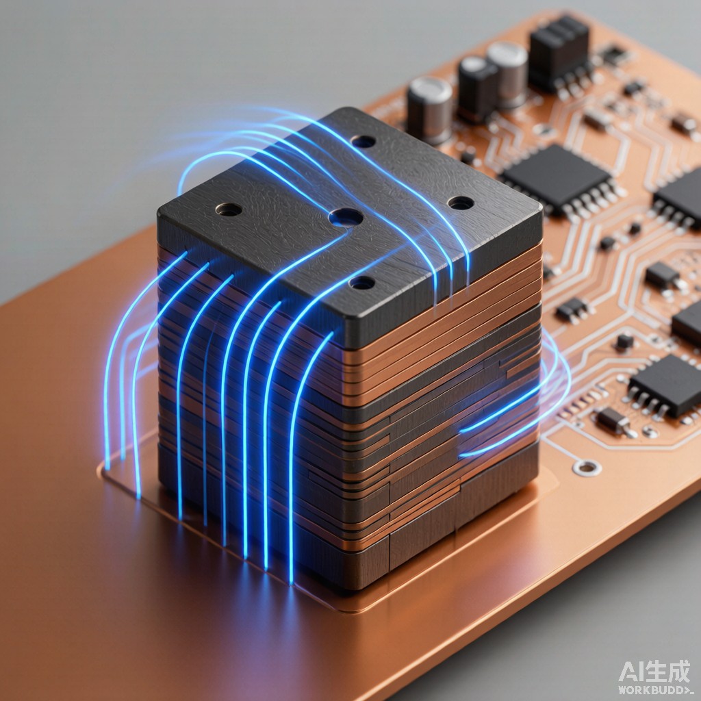
Introduction: The Low-Frequency Shielding Challenge
While most EMI shielding discussions focus on high-frequency electromagnetic interference from digital circuits and RF communications, industrial power electronics present a different and often harder problem: low-frequency magnetic field interference from switching converters, motor drives, and transformers operating in the 50 Hz to 100 kHz range. At these frequencies, conductive metal shielding (copper, aluminum) becomes ineffective because the mechanism shifts from reflection and absorption of electromagnetic waves to the redirection of quasi-static magnetic flux.
Silicon steel laminated shielding provides a cost-effective, high-saturation solution for low-frequency magnetic field management in SMT equipment enclosures, motor drive housings, and power distribution panels. This article examines the material science, design methodology, and practical implementation of silicon steel EMI shielding for power electronics applications.
Silicon Steel Material Fundamentals
Composition and Magnetic Properties
Silicon steel — also called electrical steel — is an iron-silicon alloy containing 1-6.5% silicon by weight. The addition of silicon serves three critical purposes: it increases electrical resistivity (reducing eddy current losses), it reduces magnetostriction (reducing acoustic noise), and it improves magnetic permeability in the rolling direction. For EMI shielding applications, silicon content of 3-4% provides the optimal balance of permeability, saturation flux density, and mechanical workability.
| Property | Non-Oriented Silicon Steel (3% Si) | Grain-Oriented Silicon Steel (3% Si) | Mu-Metal (80% Ni-Fe) | Ferrite (MnZn) |
|---|---|---|---|---|
| Initial Permeability (μi) | 1,000-3,000 | 5,000-15,000 | 30,000-80,000 | 1,500-5,000 |
| Maximum Permeability (μmax) | 4,000-8,000 | 30,000-80,000 | 100,000-300,000 | 3,000-10,000 |
| Saturation Flux Density (Bs) | 1.6-1.7 T | 1.8-2.0 T | 0.65-0.75 T | 0.35-0.45 T |
| Electrical Resistivity | 48 μΩ·cm | 48 μΩ·cm | 55-60 μΩ·cm | 10^6 μΩ·cm |
| Relative Cost | 1.0x | 1.5-2.0x | 15-25x | 2-4x |
| Frequency Range | 50 Hz – 10 kHz | 50 Hz – 1 kHz | DC – 30 kHz | 10 kHz – 1 MHz |
The key advantage of silicon steel over mu-metal is saturation flux density. Power electronics generate magnetic fields that can exceed 0.5 T in proximity to inductors and transformers. Mu-metal, with its Bs of only 0.75 T, saturates readily in these fields, losing its high permeability and becoming ineffective as a shield. Silicon steel, with Bs of 1.7-2.0 T, can operate in high-field environments without saturation, making it the practical choice for shielding near switching magnetics.
Grain-Oriented vs Non-Oriented Silicon Steel
Grain-oriented (GO) silicon steel undergoes a controlled rolling and a
ealing process that aligns the easy-axis of magnetization [100] crystallographic direction with the rolling direction. This produces very high permeability along one axis but significantly lower permeability in the transverse direction. GO silicon steel is ideal for applications where the magnetic field direction is known and consistent — such as transformer core shielding where flux flows along a defined path.
Non-oriented (NO) silicon steel has a more random grain structure, providing approximately equal permeability in all directions in the plane of the sheet. For EMI shielding applications where the incident magnetic field direction may vary (as in equipment enclosures exposed to multi-source interference), NO silicon steel is the appropriate choice. The trade-off is lower maximum permeability — but the isotropic behavior is essential for general-purpose shielding.
Lamination Design for Eddy Current Suppression
Why Lamination Matters
In a solid steel shield, time-varying magnetic fields induce eddy currents that oppose the field penetration (Lenz’s law). While this provides some shielding effect, the eddy currents also generate resistive (I2R) losses that heat the shield and reduce its effective permeability. At 50 Hz, the skin depth in 3% silicon steel is approximately 2.5 mm, meaning a solid shield thicker than 5 mm contributes minimal additional attenuation.
Lamination breaks the eddy current path into thin, insulated layers. The eddy current loss per layer scales with the square of the lamination thickness — halving the lamination thickness reduces eddy current loss by a factor of four. For EMI shielding, this means a laminated shield can be much more effective than a solid shield of the same total thickness.
Optimal Lamination Thickness
The optimal lamination thickness balances eddy current suppression against manufacturing cost and assembly complexity. Standard lamination thicknesses and their performance characteristics:
| Lamination Thickness | Eddy Current Loss Reduction | Typical Application | Cost Factor |
|---|---|---|---|
| 0.65 mm | Baseline (1.0x) | 50 Hz transformer cores | 1.0x |
| 0.35 mm | 3.5x reduction | 400 Hz aircraft, general shielding | 1.2x |
| 0.20 mm | 10.6x reduction | Switch-mode power supply shielding | 1.5x |
| 0.10 mm | 42x reduction | High-frequency (up to 20 kHz) shielding | 2.5x |
For most SMT equipment EMI shielding applications targeting 50 Hz to 10 kHz interference, 0.35 mm lamination thickness provides the best cost-performance ratio. The 3.5x eddy current reduction compared to 0.65 mm lamination is sufficient for effective shielding, while the cost premium is modest.
Multi-Layer Shield Design Methodology
High-Permeability / High-Saturation Hybrid Architecture
When the magnetic field environment is unknown or spans a wide range of field strengths, a single-material shield may not provide optimal performance. A hybrid multi-layer shield combines the strengths of high-saturation material (silicon steel) with high-permeability material (mu-metal or ferrite) in a layered configuration:
Layer 1 (field-facing): 1-2 mm silicon steel — handles high incident flux density without saturation, redirects the bulk of the magnetic field through its high Bs.
Layer 2 (interior): 0.5-1 mm mu-metal — operates in the reduced field after the silicon steel layer has attenuated the strongest components, providing high-permeability flux shunting for residual low-field interference.
This architecture exploits the complementary properties of both materials. The silicon steel layer sees the full field and does not saturate, while the mu-metal layer sees only the attenuated field (typically 20-30% of incident) and operates within its saturation margin. The combined shielding effectiveness at 50-500 Hz typically reaches 25-40 dB, compared to 15-25 dB for silicon steel alone and 10-15 dB for mu-metal alone (which saturates in the incident field).
Lamination Orientation and Assembly
For laminated shields, the orientation of the laminations relative to the incident field significantly affects performance. The magnetic flux should enter perpendicular to the lamination plane (crossing the insulated interfaces), not parallel to it. When flux enters parallel to the lamination plane, it encounters the full cross-section of each steel layer, and the eddy current suppression benefit is lost.
In practice, this means that laminated shield panels should be oriented with their flat faces toward the magnetic field source. For cylindrical or curved shield geometries (enclosing cables or bus bars), spiral-wound lamination construction ensures that the flux path always crosses lamination interfaces.
Practical Implementation in SMT Equipment Enclosures
Shield Placement and Grounding
Silicon steel laminated shielding is most effective when placed as close as practical to the magnetic field source — typically the switching inductor or transformer. For PCB-mounted power converters, a shield panel mounted 5-15 mm below the PCB (on the enclosure floor) can attenuate field penetration into the enclosure base by 20-35 dB at 100 kHz. The shield should be electrically bonded to the enclosure ground structure at multiple points to prevent shield resonance and provide a return path for any induced currents.
For open-frame power supplies where a full enclosure is not available, localized silicon steel shields bent into L-shaped or U-shaped configurations around the switching magnetics can provide 10-20 dB of localized field reduction, sufficient to bring near-field emissions below CISPR 32 Class B limits without adding significant cost or weight.
Tropical Climate Considerations
Silicon steel is susceptible to corrosion in humid tropical environments, particularly at the lamination interfaces where moisture can wick into the inter-layer insulation. For Southeast Asian deployments, the outermost lamination should be coated with a corrosion-resistant finish — electrolytic zinc plating (5-8 micrometers) or epoxy powder coating (50-100 micrometers). The inter-layer insulation (typically oxide or phosphate coating) provides adequate moisture resistance for indoor equipment, but for outdoor-rated enclosures, a hermetically sealed shield assembly is recommended.
Conclusion
Silicon steel laminated EMI shielding fills the performance gap between simple conductive metal shields (ineffective at low frequencies) and expensive mu-metal shields (prone to saturation in high-field environments). With saturation flux density of 1.7-2.0 T, permeability of 1,000-8,000, and costs 10-20x lower than mu-metal, silicon steel is the practical choice for low-frequency magnetic field management in industrial power electronics. Proper lamination thickness selection (0.35 mm for 50 Hz-10 kHz), hybrid layer design combining silicon steel with mu-metal for wide-dynamic-range environments, and correct orientation of laminations relative to the incident field are the key engineering decisions. With appropriate corrosion protection for tropical climates, silicon steel laminated shields provide reliable, cost-effective EMI suppression for SMT equipment deployed in Southeast Asian industrial environments.



