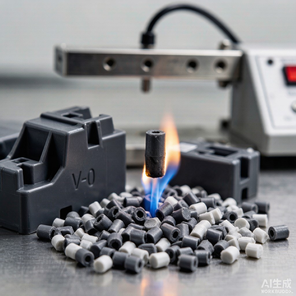
Introduction: The Flame Retardant Challenge for Cost-Sensitive Electronics
Polypropylene (PP) is the workhorse polymer of cost-sensitive electronics manufacturing, used extensively for SMT component transport trays, co
ector housings, power supply enclosures, and consumer electronics cases. At $1.2–1.8/kg, it is 60–70% cheaper than ABS and 75–80% cheaper than PC/ABS. However, neat PP is highly flammable — it ignites easily (LOI = 17–18%), drips flaming droplets that propagate fire, and burns with a high heat release rate. Achieving UL94 V-0 flame retardancy in polypropylene while maintaining its cost advantage and processability has been the central materials challenge in PP-based electronics enclosure manufacturing.
This article examines the most environmentally progressive solution: intumescent flame retardant (IFR) PP pellets based on ammonium polyphosphate / pentaerythritol / melamine (APP/PER/MEL) chemistry. We cover formulation science, mechanical property trade-offs, injection molding parameter optimization, and comparative performance against halogenated FR-PP and alternative FR polymers.
Why Intumescent FR for PP?
Halogenated vs Intumescent: The Chemistry Choice
| Parameter | Brominated FR-PP (DBDE/DecaBDE) | Brominated FR-PP (TBBA/BEO) | Intumescent FR-PP (APP/PER/MEL) |
|---|---|---|---|
| FR mechanism | Gas-phase radical quenching (Br· captures H· and OH·) | Gas-phase radical quenching | Condensed-phase char formation (intumescent barrier) |
| Typical loading for V-0 at 1.6mm | 8–12 wt% Br + 4–6 wt% Sb₂O₃ synergist | 15–20 wt% Br + 5–8 wt% Sb₂O₃ | 25–35 wt% IFR (APP:PER:MEL ≈ 3:1:1) |
| Total additive loading | 12–18 wt% | 20–28 wt% | 25–35 wt% |
| LOI (%) | 26–30 | 28–32 | 30–36 |
| Smoke density | High (corrosive, toxic HBr gas) | High (corrosive, toxic HBr gas) | Low (predominantly H₂O, CO₂, NH₃) |
| Environmental | Ba
ed under Stockholm Convention (DecaBDE, 2017) |
Regulated (RoHS, WEEE, REACH SVHC) | Halogen-free, RoHS-compliant |
| Anti-dripping | Poor without PTFE; flaming drips common | Moderate with PTFE addition | Excellent; self-extinguishing char prevents dripping |
| Tensile strength retention | 85–95% of neat PP | 80–90% of neat PP | 65–80% of neat PP |
| Cost (USD/kg, 2026) | $2.50–3.50 | $3.00–4.50 | $2.80–4.00 |
Intumescent FR systems are gaining market share rapidly because they address the two primary objections to halogenated FRs: toxic smoke emission during fire (hydrogen bromide gas is acutely corrosive and toxic to occupants) and environmental persistence (decabromodiphenyl ether and related compounds are now restricted under the Stockholm Convention on Persistent Organic Pollutants). For electronics manufacturers exporting to the EU, Japan, and increasingly Southeast Asian markets with tightening environmental regulations, the halogen-free advantage of IFR-PP translates directly to market access.
APP/PER/MEL Intumescent Chemistry
The Three-Component System
The classic intumescent formulation for polypropylene consists of three components that work synergistically:
| Component | Chemical | wt% in IFR | Function | Decomposition Temperature |
|---|---|---|---|---|
| Acid source | Ammonium Polyphosphate (APP, (NH₄PO₃)ₙ, n = 200–1,000) | 50–60% | Decomposes at 250–300°C to release phosphoric acid (H₃PO₄), which catalyzes dehydration of the carbonific agent | 250–300°C |
| Carbonific agent | Pentaerythritol (PER, C(CH₂OH)₄) | 15–20% | Dehydrates to form char precursor; provides carbon skeleton for intumescent char layer | 260–280°C |
| Spumific agent | Melamine (MEL, C₃H₆N₆) | 15–20% | Decomposes at 300–350°C to release non-flammable gases (NH₃, N₂, CO₂) that expand the char into a foam-like insulating barrier | 300–350°C |
Intumescence Mechanism
The flame retardant action of IFR-PP occurs through a sequential condensed-phase mechanism:
- Stage 1 — Acid release (250–300°C): APP thermally decomposes to liberate phosphoric acid and polyphosphoric acid. The acid diffuses into the decomposing PP matrix, catalyzing dehydration and cross-linking reactions.
- Stage 2 — Char formation (270–350°C): The phosphoric acid esterifies and dehydrates the pentaerythritol, forming a carbon-rich char precursor. Melamine begins to decompose, releasing ammonia and nitrogen gases.
- Stage 3 — Intumescent expansion (300–450°C): The released gases (NH₃, N₂, H₂O vapor, CO₂) expand the char precursor into a multicellular foam structure with volume expansion of 50–100× the original thickness. This expanded char layer has extremely low thermal conductivity (0.02–0.05 W/m·K) and acts as a physical barrier between the underlying PP and the heat source.
- Stage 4 — Barrier protection (450°C+): The stable, phosphorus-rich char shield insulates the unburned PP, blocks oxygen diffusion, and traps flammable decomposition gases — simultaneously addressing all three elements of the fire triangle.
The critical performance metric is the mass ratio of char residue at 600°C under nitrogen (TGA measurement). An IFR-PP formulation achieving V-0 typically yields 15–25% char residue at 600°C, compared to < 1% for neat PP. Higher char yield correlates directly with better flame retardancy.
Synergists: Boosting IFR Efficiency
At 25–35 wt% loading, IFR additives significantly degrade PP mechanical properties. Synergists reduce the required IFR loading while maintaining V-0 performance:
| Synergist | Loading (wt%) | IFR loading reduction | Mechanism |
|---|---|---|---|
| Zinc borate (2ZnO·3B₂O₃·3.5H₂O) | 2–5 | 5–10 wt% reduction in IFR | Forms glassy borate layer; stabilizes char at high temperature; suppresses afterglow |
| Montmorillonite nanoclay (MMT) | 1–3 | 3–7 wt% reduction in IFR | Platelet barrier reduces heat and mass transfer; increases char strength and integrity |
| Expandable graphite (EG) | 3–8 | 5–15 wt% reduction in IFR | Physical expansion (150–300×) adds mechanical char reinforcing; “worm-like” expanded graphite locks char structure |
| Metal oxides (TiO₂, CeO₂, La₂O₃) | 0.5–2 | 2–5 wt% reduction in IFR | Catalytic effects on cross-linking; radical trapping at char surface |
An optimized formulation for SMT electronics enclosures: PP + 20 wt% IFR (APP/PER/MEL 3:1:1) + 3 wt% expandable graphite + 2 wt% zinc borate achieves UL94 V-0 at 1.6 mm with total additive loading of 25 wt% — significantly lower than the 30–35 wt% required without synergists. This 5–10 wt% reduction in additive loading translates to a 15–25% improvement in tensile strength and impact resistance.
Mechanical Property Trade-Offs
Performance at Target Formulation
| Property | Neat PP (homopolymer) | IFR-PP (25 wt% additive, with synergists) | Retention vs Neat PP | UL94 V-0 Requirement Relevance |
|---|---|---|---|---|
| Tensile strength (MPa) | 32–38 | 24–28 | 72–78% | Enclosure structural integrity — still adequate for non-load-bearing |
| Flexural modulus (GPa) | 1.2–1.6 | 1.5–2.0 | 115–130% | Increased stiffness due to rigid IFR particles; beneficial for snap-fit enclosures |
| Izod impact (J/m, notched, 23°C) | 25–45 | 15–25 | 55–65% | Reduced impact resistance is primary mechanical penalty; drop-test may fail |
| Elongation at break (%) | 100–600 | 5–20 | 5–15% | Ductile-to-brittle transition; design snap-fits with larger radii |
| HDT (°C, 0.45 MPa) | 100–110 | 115–130 | 110–120% | Improved — beneficial for electronics operating at elevated temperature |
| Melt flow index (g/10min, 230°C/2.16kg) | 10–30 | 5–15 | 50% reduction | Lower flow length; may require higher injection pressure and temperature |
| Density (g/cm³) | 0.90–0.91 | 1.05–1.12 | 117–123% | 15–23% heavier enclosures; account for in design weight budget |
The 35–45% reduction in Izod impact strength is the most critical limitation of IFR-PP for electronics enclosures. Sharp corners, thin snap-fit features (< 1.5 mm), and screw bosses designed for neat PP will fail in IFR-PP. Mitigation strategies include:
- Increasing snap-fit root radius from 0.5 mm to ≥ 1.0 mm
- Adding 3–5 wt% impact modifier (EPDM or POE elastomer) — recovers 50–70% of impact loss but reduces UL94 rating from V-0 to V-1; requires formulation re-optimization
- Designing enclosure wall thickness ≥ 2.0 mm at all structural features
- Avoiding weld-line locations at mechanical stress concentrations (gate location optimization)
Injection Molding Parameter Optimization
Critical Processing Adjustments
| Parameter | Neat PP | IFR-PP (25 wt%) | Rationale for Adjustment |
|---|---|---|---|
| Barrel temperature profile (°C) | 190-200-210-220 | 180-185-190-200 | Lower temperatures prevent premature APP decomposition (onset at ~250°C) and melamine sublimation |
| Mold temperature (°C) | 30–50 | 40–60 | Higher mold temp improves surface finish and reduces frozen-in stress at char particle interfaces |
| Injection speed | Medium to high | Medium | Excessive shear heating at high speed (>200 mm/s) raises melt temp above APP decomposition threshold |
| Back pressure (bar) | 5–10 | 5–8 | Lower back pressure reduces shear heating; IFR particles disperse adequately at low shear |
| Screw speed (rpm) | 100–150 | 80–100 | Minimizes frictional heating in the compression zone |
| Screw type | General-purpose (L/D = 20–24) | Low-shear mixing screw (L/D = 24–28, Maddock or pineapple mixer) | Dispersive mixing elements break up IFR agglomerates without excessive shear |
| Drying | Not typically required | 80–90°C, 2–3 hours | APP is hygroscopic; moisture causes splay marks and hydrolysis of phosphate ester char precursor |
Thermal Degradation Risk
The processing window for IFR-PP is narrower than for neat PP due to the overlap between the PP melting range (165–170°C) and the onset of APP decomposition (250°C). The maximum safe melt temperature is 210–220°C — only 40–55°C above the melt temperature, compared to a 50–80°C window for neat PP. Exceeding 220°C for more than 2–3 minutes causes:
- Phosphoric acid release within the barrel, causing corrosion of screw and barrel surfaces (phosphoric acid attacks nitrided steel at 200°C+)
- Pre-crosslinking and viscosity increase (char formation inside the barrel)
- Discoloration (yellowing to brown) of molded parts
- Loss of flame retardant effectiveness due to premature consumption of the acid source
For production runs exceeding 4 hours, periodic purging with unfilled PP (every 2–3 hours) is recommended to clear partially degraded IFR residue from the barrel and prevent accumulation on the screw.
Flame Retardancy Testing and Standards
UL94 Vertical Burn Test (V-0 Criteria)
For SMT electronics enclosures, UL94 V-0 at the minimum enclosure wall thickness (typically 1.5–2.0 mm) is the universal requirement. The V-0 criteria for a 125 mm × 13 mm specimen are:
- Afterflame time after each 10-second flame application: ≤ 10 seconds (per specimen)
- Sum of afterflame times for 5 specimens (10 flame applications): ≤ 50 seconds
- Afterflame + afterglow after second flame: ≤ 30 seconds
- No flaming drips that ignite cotton indicator
- No afterglow to the holding clamp
Glow Wire Testing (IEC 60695-2-11)
For unattended appliances (> 0.2 A), the glow wire ignition temperature (GWIT) and glow wire flammability index (GWFI) are required. IFR-PP with 25 wt% additive achieves:
| Test | Pass Temperature | Requirement for Unattended Appliance |
|---|---|---|
| GWFI (IEC 60695-2-12) | 850°C | 750°C (≥ 0.2 A); 850°C (> 0.5 A) |
| GWIT (IEC 60695-2-13) | 775°C | 750°C minimum |
IFR-PP outperforms many halogenated FR-PP formulations in glow wire testing because the intumescent char layer, once formed, maintains structural integrity at the high contact temperatures (750–960°C) of the glow wire test — whereas halogenated systems that rely on gas-phase radical quenching offer no physical barrier to the heated wire.
Comparison with Alternative FR Materials for SMT Enclosures
| Material | FR Type | Density (g/cm³) | Tensile (MPa) | Impact (J/m) | Cost ($/kg) | Best Application |
|---|---|---|---|---|---|---|
| IFR-PP (25% additive) | Intumescent (halogen-free) | 1.08 | 26 | 20 | 3.20 | Cost-sensitive consumer electronics enclosures |
| Brominated FR-PP | Halogenated + Sb₂O₃ | 1.12 | 30 | 30 | 3.00 | Applications where halogen is acceptable and higher impact needed |
| FR-ABS (brominated) | Halogenated | 1.18 | 40 | 180 | 3.80 | Premium enclosures requiring high impact |
| Halogen-free FR PC/ABS | Phosphorus-based (RDP/BDP) | 1.15 | 55 | 450 | 5.50 | High-performance IT/telecom enclosures |
| IFR-PP with 5% GF reinforcement | Intumescent (halogen-free) | 1.12 | 35 | 30 | 3.50 | SMT enclosures requiring higher stiffness and HDT |
Southeast Asian Supply Chain and Processing Considerations
In tropical manufacturing environments:
- Moisture management: IFR-PP pellets must be stored in sealed, moisture-barrier packaging. At 80–95% RH (typical SE Asian warehouse), pellets absorb 0.05–0.15% moisture within 4 hours of exposure — sufficient to cause splay defects. Dryer hoppers with -40°C dew point are recommended for production runs.
- Regulatory landscape: Thailand, Vietnam, and Indonesia are progressively adopting IEC 62368-1 (safety requirements for audio/video and IT equipment), which mandates glow wire testing for enclosure materials. Malaysia and Singapore already enforce these requirements. IFR-PP’s strong glow wire performance positions it well for this regulatory transition.
- Cost competitiveness: IFR-PP at $3.20/kg is 40% cheaper than halogen-free FR PC/ABS at $5.50/kg, while meeting the same UL94 V-0 requirement. For a 100 g enclosure, the material cost saving is approximately $0.23 per unit — significant in high-volume SMT accessory manufacturing.
Conclusion
Intumescent flame retardant polypropylene represents the most environmentally sustainable and cost-competitive route to UL94 V-0 compliance for SMT electronics enclosures. While the 25–35 wt% additive loading imposes trade-offs in impact strength and melt flow, formulation optimization with synergists (expandable graphite, zinc borate, nanoclay) reduces the loading penalty without sacrificing V-0 performance. For Southeast Asian electronics manufacturers navigating tightening environmental regulations and demanding glow wire test requirements, IFR-PP provides a halogen-free, RoHS-compliant solution that maintains the critical $2–3/kg cost advantage of polypropylene over engineering thermoplastics. The key to successful implementation is disciplined injection molding process control — maintaining melt temperatures below 210°C, pre-drying pellets to < 0.05% moisture, and designing enclosure features to accommodate the reduced impact strength of the flame-retarded material.



