Introduction: Why ESD-Safe Trays Matter in SMT Manufacturing
Electrostatic discharge (ESD) is the silent killer of SMT electronics manufacturing. A single 100V discharge — imperceptible to humans who typically feel discharges only above 3,000V — can destroy or degrade sensitive semiconductor devices including BGA packages, MEMS sensors, and RF ICs. Industry estimates attribute 8–33% of all electronics field failures to ESD damage incurred during handling, transport, and storage.
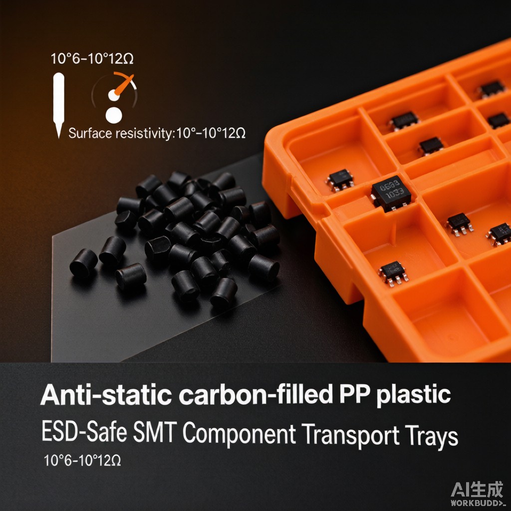
Injection-molded transport trays made from anti-static carbon-filled polypropylene (PP) pellets are the primary defense against ESD in SMT production lines. These trays safely dissipate static charges while providing the mechanical protection, dimensional precision, and thermal stability required for automated pick-and-place handling. This article examines the material science, filler selection, and manufacturing considerations for ESD-safe PP tray production.
ESD Classification and Surface Resistivity Standards
Resistance Classification per ANSI/ESD S541
| Classification | Surface Resistance (Ω) | Volume Resistance (Ω) | Application |
|---|---|---|---|
| Insulative | ≥1 × 10¹¹ | ≥1 × 10¹¹ | NOT for ESD-sensitive items |
| Static Dissipative | ≥1 × 10⁴ to <1 × 10¹¹ | ≥1 × 10⁴ to <1 × 10¹¹ | General ESD-safe trays, tote boxes |
| Conductive (Low Charging) | <1 × 10⁴ | <1 × 10⁴ | Direct contact IC trays, shielding bags |
For SMT component transport trays, the static dissipative range (10⁶–10⁹ Ω) is the most commonly specified classification. This range provides sufficient conductivity to bleed off triboelectric charges within milliseconds (preventing charge accumulation above 100V) while avoiding the rapid discharge currents associated with conductive materials that could themselves damage sensitive devices through charged device model (CDM) events.
Triboelectric Charging Mechanism
When SMT components are placed into or removed from trays, friction between the component leads/body and the tray surface generates triboelectric charges. Unfilled PP (insulative, 10¹⁴–10¹⁶ Ω) allows these charges to accumulate to thousands of volts. Carbon-filled PP reduces surface resistance to the dissipative range, allowing charges to drain through the tray to a grounded surface at a controlled rate. The charge decay time (t) follows:
t = R × C (where R = surface resistance, C = capacitance)
For a tray with surface resistance 10⁸ Ω and typical capacitance of 50 pF, the charge decay time constant is 5 milliseconds — fast enough to prevent dangerous charge accumulation during normal handling operations (which take 0.5–2 seconds).
Carbon Filler Selection: Carbon Black vs CNT vs Graphene
Filler Material Comparison
| Property | Carbon Black (CB) | Carbon Nanotube (CNT) | Graphene Nanoplatelet (GNP) |
|---|---|---|---|
| Particle shape | Spherical (aggregates) | Tubular (1D) | Platelet (2D) |
| Aspect ratio | 1–5 | 100–10,000 | 500–5,000 |
| Percolation threshold (wt%) | 8–15 | 0.5–2.0 | 1.0–3.0 |
| Typical loading for 10⁸ Ω | 10–15 wt% | 1.5–3.0 wt% | 2.0–4.0 wt% |
| Surface resistivity range | 10⁶–10¹⁰ Ω | 10³–10⁸ Ω | 10⁴–10⁹ Ω |
| Color (at functional loading) | Black (opaque) | Dark gray (opaque) | Black (opaque) |
| Tensile strength retention | 70–80% of neat PP | 85–95% of neat PP | 80–90% of neat PP |
| Izod impact retention | 60–75% of neat PP | 80–90% of neat PP | 70–85% of neat PP |
| Cost (USD/kg, 2026) | 3–8 | 300–1,000 | 50–200 |
| Cost per tray (filler only) | $0.10–0.25 | $0.80–2.50 | $0.30–0.80 |
Carbon black dominates the SMT tray market due to its extremely low cost and well-established compounding technology. However, its high loading requirement (10–15 wt%) significantly degrades mechanical properties — particularly impact strength, which drops by 25–40%. This makes carbon black-filled trays brittle and prone to cracking during automated handling, especially at low temperatures (below 10°C) common in air-conditioned SMT cleanrooms.
MWCNT (multi-walled carbon nanotube) fillers offer the best property retention at functional loading but are prohibitively expensive for commodity tray applications. They find use in high-value applications such as JEDEC trays for bare semiconductor wafers and test sockets where mechanical precision is paramount.
Hybrid Filler Strategy
A growing trend in ESD-safe tray manufacturing is the use of hybrid filler systems combining carbon black (4–6 wt%) with a small amount of CNT or graphene (0.5–1.0 wt%). This approach achieves the target surface resistivity at 30–40% lower total filler loading compared to carbon black alone, improving mechanical properties by 15–25% while keeping material cost under $0.50 per tray.
Injection Molding Parameters for Carbon-Filled PP
Processing Considerations
Carbon fillers modify the rheological and thermal properties of PP, requiring adjusted molding parameters:
| Parameter | Neat PP | CB-filled PP (12 wt%) | CNT-filled PP (2 wt%) | Notes |
|---|---|---|---|---|
| Melt temperature (°C) | 200–240 | 210–250 | 200–240 | CB increases thermal degradation risk |
| Mold temperature (°C) | 30–50 | 40–60 | 30–50 | Higher mold temp improves surface finish |
| Injection pressure (bar) | 800–1,200 | 1,000–1,500 | 900–1,300 | Higher viscosity from filler |
| Cooling time (s) | 15–25 | 10–20 | 12–22 | CB improves thermal conductivity, faster cooling |
| Screw speed (rpm) | 100–150 | 80–120 | 80–120 | Lower to minimize filler degradation |
| Back pressure (bar) | 5–10 | 10–20 | 10–15 | Higher for better dispersion |
Critical Defect: Filler Sloughing
Excess carbon filler on the tray surface — known as sloughing or rub-off — is a critical defect that contaminates SMT components with conductive particles. ANSI/ESD S541 limits sloughing to <0.05 mg per 100 cm² of contact area. Sloughing is caused by poor filler-matrix adhesion and excessive surface filler concentration, typically resulting from:
- Over-filling (loading above percolation threshold by >3 wt%)
- Inadequate dispersion (agglomerates >10 μm)
- Excessive mold release agent
- Rough mold surface (Ra > 0.4 μm)
Mitigation requires tight compounding quality control (twin-screw extruder with L/D ≥ 40, dispersive mixing elements), polished mold cavities (Ra < 0.2 μm), and minimal use of mold release. Post-molding surface treatment (flame or plasma) can improve filler-matrix bonding at the surface, reducing sloughing by 60–80%.
Tray Design for ESD Performance
Pocket Geometry and Charge Dissipation
Effective ESD protection requires that every point on the tray surface has a continuous conductive path to the grounding point. Deep pockets with high aspect ratios (depth/width > 0.8) can create isolated zones where filler concentration is lower due to flow limitations during molding. Design guidelines include:
- Maximum pocket depth-to-width ratio: 0.7 (for carbon black-filled PP)
- Minimum wall thickness: 1.0 mm (ensures filler continuity through cross-section)
- Grounding features: at least one flat contact pad (≥20 mm × 20 mm) on the tray base
- Co
ecting ribs: 2 mm minimum width between pockets to maintain conductive pathways
Thermal Performance for Reflow-Safe Trays
Some SMT applications require trays that withstand reflow oven temperatures (260°C peak for Pb-free). Standard PP (melting point 165°C) ca
ot survive reflow. For these applications, carbon-filled PPS or LCP is used instead. However, for standard transport and storage (non-reflow), carbon-filled PP with HDT of 110–130°C (at 0.45 MPa) provides adequate thermal margin for warehouse and cleanroom environments where temperatures rarely exceed 40°C.
Southeast Asian Manufacturing Considerations
In tropical manufacturing environments (30–35°C, 80–95% RH), several factors affect ESD-safe tray performance:
- Moisture absorption: PP is hydrophobic (<0.02% water absorption), so humidity has minimal effect on surface resistivity. However, surface condensation at dew point can temporarily reduce resistivity by 1–2 decades, which is generally beneficial for ESD protection.
- Temperature effect: Surface resistivity of carbon-filled PP decreases by approximately 0.5 decade per 10°C temperature increase. At 35°C, trays may measure 5 × 10⁷ Ω instead of the 1 × 10⁸ Ω measured at 23°C — still within the dissipative range.
- UV degradation: Carbon black provides excellent UV screening, making carbon-filled PP trays suitable for outdoor transit applications where clear PP would degrade rapidly.
Quality Control Testing
| Test | Method | Acceptance Criteria | Frequency |
|---|---|---|---|
| Surface resistance | ANSI/ESD S541 (flat probe) | 10⁶–10⁹ Ω | 1 tray per 500 |
| Sloughing | ANSI/ESD S541 (tape test) | <0.05 mg/100 cm² | 1 tray per 1,000 |
| Charge decay time | MIL-STD-1686 / IEC 61340-5-1 | <2 seconds (5kV to 50V) | 1 tray per batch |
| Dimensional stability | CMM measurement | ±0.15 mm pocket position | First article + 1/hr |
| Impact resistance | ASTM D256 (Izod notched) | ≥40 J/m (at 23°C) | 1 per material lot |
Conclusion
Anti-static carbon-filled PP pellets provide a cost-effective, reliable solution for ESD-safe SMT component transport trays. Carbon black remains the dominant filler for commodity trays due to its low cost, while hybrid CB-CNT systems offer improved mechanical performance for high-precision applications. By controlling filler loading within the percolation window, optimizing injection molding parameters, and implementing rigorous QC testing, Southeast Asian tray manufacturers can produce ESD-safe products that protect sensitive semiconductor devices throughout the SMT supply chain — from die attach to final board assembly.



