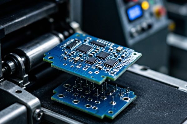
The Challenge of Placing Heavy Metal Components on SMT Lines
Modern SMT pick-and-place machines were designed for lightweight silicon components—ICs, resistors, capacitors, and inductors weighing from 0.01 mg (0201 passive) to about 5 grams (large QFPs). But as electronics manufacturing evolves, more products require placing heavier metal components directly on the PCB: copper EMI shielding cans (2–15 g), brass RF co
ector shells (3–8 g), copper busbar jumpers (5–20 g), and stamped copper alloy contacts (0.5–3 g). These components challenge every aspect of the pick-and-place process, from vacuum grip reliability to placement accuracy and solder paste displacement.
This article covers the practical engineering adjustments needed to reliably place heavy copper and brass components on high-speed SMT lines.
Vacuum Nozzle Selection for Heavy Components
Nozzle Bore and Suction Force Calculation
The vacuum force holding a component is: F = P × A, where P is the vacuum pressure differential (typically 60–85 kPa for standard SMT vacuum pumps) and A is the effective suction area. For a component weighing m grams, the required suction force must exceed F = m × g × safety_factor, where the safety factor accounts for acceleration during gantry movement (typically 3–5× for high-speed placement).
For a 10 g copper shielding can with a 5× safety factor: Required force = 10g × 9.81 m/s² × 5 = 0.49 N. At 70 kPa vacuum, the minimum nozzle bore area needed is 0.49 / 70,000 = 7.0 mm², corresponding to a bore diameter of approximately 3.0 mm. However, this assumes the component surface is flat and provides a perfect seal—rarely the case with stamped metal parts.
Nozzle Tip Material and Geometry
- Standard ceramic nozzles: Suitable for flat-top components up to 5 g. Ceramic tips provide a hard, smooth sealing surface but chip easily if the component has burrs from stamping.
- Delrin (acetal) nozzles: Soft enough to conform to slightly uneven surfaces, providing better vacuum sealing on stamped metal components with minor surface irregularities. Recommended for copper and brass components from 2–10 g.
- Custom silicone bellows nozzles: For components with irregular geometries (angled shields, co
ector shells with cavities), a silicone bellows tip can conform to the surface and maintain vacuum seal. These nozzles are custom-machined to match the component profile and are essential for brass co
ector shells with concave or angled pickup surfaces.
- Multi-bore nozzles: For large, flat components like EMI shielding cans (40 × 40 mm or larger), a multi-bore nozzle with 4–9 suction points distributes the vacuum force across the component surface, preventing tilting and providing more reliable pickup.
Vacuum System Upgrades
Standard SMT machine vacuum pumps typically generate 60–80 kPa. For components above 15 g, consider upgrading to a high-vacuum pump (90–100 kPa) or adding a vacuum booster. Some machines offer a “heavy component” mode that increases vacuum pressure for a specified range of feeder positions while maintaining standard vacuum for lighter components.
Vision System Calibration for Reflective Metal Surfaces
Copper and brass components present a unique challenge for machine vision: their highly reflective surfaces can saturate the camera sensor, creating bright spots that confuse the vision algorithm’s edge detection. This is particularly problematic for brass components, which reflect both the overhead lighting and the background of the machine.
Lighting Adjustments
- Reduce top-light intensity: Standard SMT machine top lights are optimized for matte-finish components (black ICs, gray passives). For reflective metal parts, reduce top light to 30–50% of standard intensity and increase side light (if available) to highlight component edges rather than surface reflections.
- Use polarized lighting: Some high-end machines offer polarized light options that suppress specular reflections from metallic surfaces. If available, this is the most effective solution for reliable vision alignment of copper and brass components.
- Blue illumination: Blue-wavelength LED illumination reduces the contrast between bright reflections and the component body on copper surfaces, providing more consistent edge detection than white light.
Alignment Feature Selection
For stamped metal components, the vision system should align on physical features rather than surface patterns:
- Outer edges: The component silhouette is the most reliable alignment feature for metal parts. Program the vision system to use the outer boundary for X-Y alignment and rotation.
- Stamped holes or notches: Many EMI shielding cans and co
ector shells have alignment holes or notches that provide precise vision fiducials. These features are more reliable than edge-based alignment because they are less affected by surface reflectivity.
- Corner features: The internal corners of rectangular shield cans provide stable alignment points that are less affected by edge burrs or surface contamination.
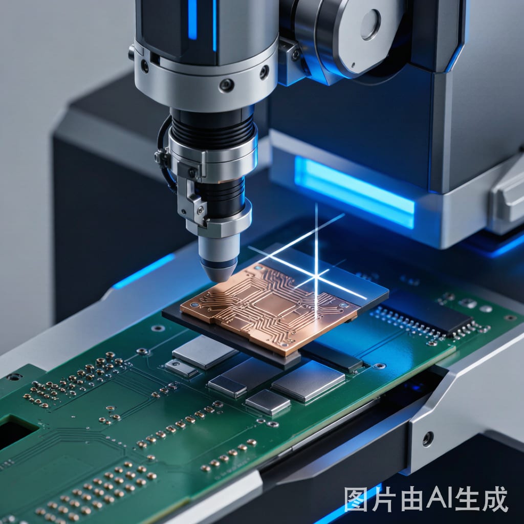
Placement Force Control
The Solder Paste Displacement Problem
When a heavy component is placed onto solder paste, the placement force must be carefully controlled. Too much force pushes the component through the solder paste and into direct contact with the copper pads, displacing paste onto adjacent areas and causing solder ball defects. Too little force leaves the component sitting on top of the paste without adequate pad contact, leading to tombstoning or misalignment during reflow.
The ideal placement force for a heavy metal component is just enough to embed the component leads 50–70% into the solder paste deposit. For a typical SAC305 solder paste with 100–120 μm stencil thickness, this means approximately 30–80 μm of paste compression. The required force depends on the paste viscosity and the total lead contact area.
Machine Settings for Heavy Components
- Placement speed: Reduce the placement speed to 50–70% of the standard setting for components above 5 g. This prevents the impact momentum from overshooting the target paste compression depth.
- Placement force: Set the placement force to the component weight plus 20–30% (e.g., for a 10 g component, use 12–13 g of placement force). This provides adequate paste penetration without excessive displacement.
- Dwell time: Increase the placement dwell time (the time the nozzle holds the component against the paste) to 100–200 ms. This allows the paste to flow around the component leads and establish adhesion before the nozzle retracts.
- Nozzle retraction speed: Use a slow nozzle retraction speed (20–30% of standard) to prevent the vacuum release from disturbing the component position on the paste.
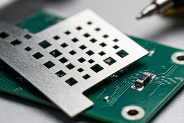
Feeder Setup for Stamped Metal Components
Stamped copper and brass components are typically supplied in tape-and-reel packaging (per IEC 60286-3) or in bulk trays. Each format has specific setup requirements:
Tape-and-Reel
Heavy metal components in tape require wider carrier tape (32 mm, 44 mm, or 56 mm) and reinforced reel hubs. Standard 8 mm and 12 mm tape may not support the component weight without tape distortion. Ensure the feeder brake tension is increased to prevent the heavier reel from unspooling under inertia during rapid feeder advances.
Bulk Trays
For large or irregularly shaped metal components (shield cans, co
ector shells), matrix trays are common. The tray pockets must be sized to hold the components with ≤0.5 mm of play to prevent shifting during gantry acceleration. Use anti-static conductive trays for components with bare metal surfaces that could short adjacent PCB traces if dropped.
Waffle Pack with Orientation Control
For asymmetric metal parts (L-shaped shields, co
ector shells with keying features), waffle packs with molded orientation features ensure consistent pickup geometry. The additional cost of custom waffle packs is justified by the reduction in vision alignment failures and misoriented placements.
Process Verification and Quality Metrics
After optimizing pick-and-place settings for heavy metal components, verify the process with these metrics:
- Pick success rate: Target ≥99.5% for metal components. Below 99% indicates nozzle or vacuum issues.
- Placement accuracy: Measure with AOI or manual microscope. Target ±100 μm for metal components (vs. ±50 μm for standard ICs), acknowledging that the heavier component mass makes fine alignment more challenging.
- Post-reflow position shift: Heavy components can shift during reflow due to solder surface tension. Measure position before and after reflow; shift should be ≤150 μm.
- Solder ball count: Monitor for solder ball defects near heavy component placement sites, which indicate excessive placement force displacing solder paste.
Conclusion
Placing heavy copper and brass components on SMT lines is not a standard pick-and-place operation—it requires deliberate optimization of nozzle selection, vacuum force, vision alignment, placement mechanics, and feeder configuration. The key principles are: size the nozzle and vacuum to the component weight with a generous safety factor, calibrate the vision system for reflective surfaces, control placement force to avoid solder paste displacement, and use appropriate packaging formats that maintain component orientation. With these adjustments, modern SMT equipment can reliably place metal components up to 20 g at throughputs that justify inline placement over manual assembly.