Springback: The Persistent Challenge in Copper Strip Stamping
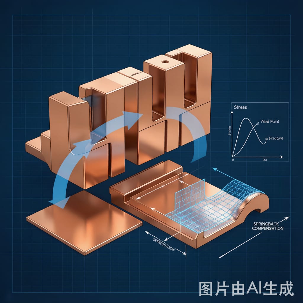
When a copper strip is bent in a progressive die stamping operation, the material undergoes both elastic and plastic deformation. Upon removal of the bending force, the elastic portion of the deformation recovers—this is springback. The bent part “springs back” toward its original flat shape by an angle that depends on the material’s yield strength, elastic modulus, bend geometry, and grain direction. For precision electronic components with tolerances of ±0.05 mm or tighter, uncontrolled springback is the difference between a part that fits and a part that scrap.
In copper alloy stamping, springback angles typically range from 1° to 8° depending on the alloy and temper. This article covers the metallurgical and geometric factors that drive springback, practical tooling compensation strategies, and material specification guidelines for minimizing springback variability in production.
The Physics of Springback in Copper Alloys
Springback Ratio and Key Parameters
The springback ratio (K) is defined as the ratio of elastic strain to total strain during bending. It can be approximated as: K = (σ_y × R) / (E × t), where σ_y is the yield strength, R is the bend radius, E is the elastic modulus, and t is the material thickness. Higher K values indicate more springback.
This equation reveals the three primary drivers of springback:
- Higher yield strength → more springback: Half-hard and hard temper copper strips spring back significantly more than soft (a
ealed) tempers. A C2680 brass strip in half-hard temper (σ_y ≈ 350 MPa) exhibits roughly 2.5× the springback of the same alloy in soft temper (σ_y ≈ 130 MPa).
- Larger bend radius → more springback: A bend radius of 5× material thickness produces approximately 3× the springback of a bend radius of 1× thickness, because a larger radius means a greater proportion of the bending strain is elastic.
- Lower elastic modulus → more springback: Copper alloys with lower elastic modulus (phosphor bronze, E ≈ 110 GPa) spring back more than those with higher modulus (beryllium copper, E ≈ 131 GPa) at the same yield strength and geometry.
Grain Direction Effects
Copper strip is rolled from ingots, creating a pronounced grain direction (rolling direction). Bending perpendicular to the rolling direction (across the grain) typically produces 15–30% more springback than bending parallel to the rolling direction (along the grain). This is because the elongated grain structure resists deformation more effectively across its long axis. In precision stamping, the strip feeding direction must be specified relative to the bend axis, and the material certificate should confirm the rolling direction.
Springback by Copper Alloy and Temper
| Alloy | Temper | Yield Strength (MPa) | Elastic Modulus (GPa) | Typical Springback (°) at R/t=3 |
|---|---|---|---|---|
| C11000 (ETP Copper) | Soft (O60) | 70 | 117 | 0.5–1.5 |
| C11000 (ETP Copper) | Half-Hard (H01) | 250 | 117 | 2.0–3.5 |
| C11000 (ETP Copper) | Hard (H04) | 340 | 117 | 3.5–5.5 |
| C26800 (Yellow Brass) | Soft (O60) | 130 | 110 | 1.0–2.0 |
| C26800 (Yellow Brass) | Half-Hard (H01) | 350 | 110 | 3.0–5.0 |
| C51000 (Phosphor Bronze) | Half-Hard (H01) | 380 | 110 | 3.5–5.5 |
| C17200 (Beryllium Cu) | Quarter-Hard (H02) | 450 | 131 | 3.0–4.5 |
| C75200 (Nickel Silver) | Half-Hard (H01) | 400 | 127 | 3.0–5.0 |
Note: These are typical values for 0.5 mm thickness. Actual springback varies with thickness, tool condition, and lubrication.
Tooling Compensation Strategies
1. Overbend Compensation
The most common approach is to design the die with an overbend angle equal to the expected springback. If the target angle is 90° and the expected springback is 4°, the die is cut to 86° so that the part springs back to 90° after unloading.
Overbend compensation requires accurate springback prediction. For simple bends, rule-of-thumb tables (like the one above) provide a starting point. For complex progressive die operations with multiple sequential bends, FEA (finite element analysis) simulation provides more accurate predictions. Modern stamping simulation software (AutoForm, PAM-STAMP, DEFORM) can predict springback within ±1° for most copper alloys when the material model includes proper strain-hardening parameters.
2. Coining (Bottoming)
Coining forces the material to conform exactly to the die profile at the bottom of the press stroke by applying high pressure (typically 3–5× the bending force). Under coining conditions, the material undergoes additional plastic deformation that reduces the elastic strain component, minimizing springback to less than 1° regardless of alloy or temper.
The trade-off is higher press to
age requirements, faster die wear, and the risk of material thi
ing at the bend line. Coining is most effective for thick materials (≥0.5 mm) with tight bend radii (R/t ≤ 2). It is not recommended for thin foils (<0.2 mm) where the coining force may exceed the material's through-thickness compression strength.
3. Wiper Die Bending
A wiper die uses a rotating bending punch that maintains continuous contact with the material throughout the bend, unlike a V-die which only contacts the material at the punch tip and die shoulders. The sustained contact and friction reduce springback by 30–50% compared to V-die bending for the same material and geometry. Wiper dies are standard in progressive stamping tools for electronic co
ector contacts and EMI shielding clips.
4. Variable Blank Holder Force
In progressive die operations, applying controlled blank holder force during bending restrains the material from flowing freely, introducing tensile stress that reduces the elastic strain component. Modern servo presses can vary the blank holder force in real-time during the bending stroke, optimizing the stress state to minimize springback on a per-bend basis. This approach requires a servo press with multi-point cushion control but can reduce springback by 40–60% without die modification.
Material Specification Best Practices
Controlling springback in production starts with controlling the incoming material. Key specification requirements:
- Specify temper, not just hardness: Two lots of “half-hard” brass may have hardness values within spec but yield strength variations of ±15%, producing springback variations of ±1.5°. Specify the temper designation per ASTM B36 (e.g., H01) and require mill certificates with yield strength, tensile strength, and elongation values.
- Tight grain size specification: Fine-grained copper strip (ASTM grain size 6–8) exhibits more consistent springback than coarse-grained material (grain size 3–5) because fine grains distribute plastic deformation more uniformly. Specify a maximum grain size of 6 for precision stamped parts with tolerances below ±0.1 mm.
- Rolling direction documentation: Require the mill to mark the rolling direction on the coil packaging and certificate. In the stamping die design, align the strip feed direction with the required bending orientation.
- Thickness tolerance: Springback is inversely proportional to thickness for a given bend radius. A +5% thickness variation (e.g., 0.50 mm ±0.025 mm) produces approximately a +5% springback variation. For the tightest tolerance parts, specify thickness tolerance of ±0.01 mm or better.
FEA-Based Springback Prediction Workflow
For new progressive die designs, a simulation-based workflow reduces die tryout iterations:
- Obtain material test data: Tensile test (true stress-strain curve), r-value (plastic strain ratio), and springback test (VDA 238-100) data from the material supplier.
- Build FEA model: Import the die CAD geometry, apply the material model with strain-rate sensitivity, and simulate the forming process including blank holder force and punch velocity.
- Springback simulation: After the forming step, release all tool contact and allow the part to spring back elastically. The simulation predicts the final part geometry and springback angle.
- Die compensation: Apply the inverse of the predicted springback displacement to the die surfaces. Re-run the simulation to verify the compensated geometry produces the target part shape.
- Iterate: Typically 2–3 compensation iterations achieve convergence within ±0.5° of the target angle.
Conclusion
Copper strip springback in progressive die stamping is a predictable, manageable phenomenon when the material properties, bend geometry, and tooling design are properly characterized. The most effective approach combines material specification control (tight temper, grain size, and thickness tolerance), FEA-based die compensation during the design phase, and process controls (coining, wiper dies, or variable blank holder force) during production. The investment in upfront simulation and material specification pays for itself in reduced die tryout time, lower scrap rates, and more consistent production output.