Why Reflow Profile Optimization Is Critical for Mixed Assemblies
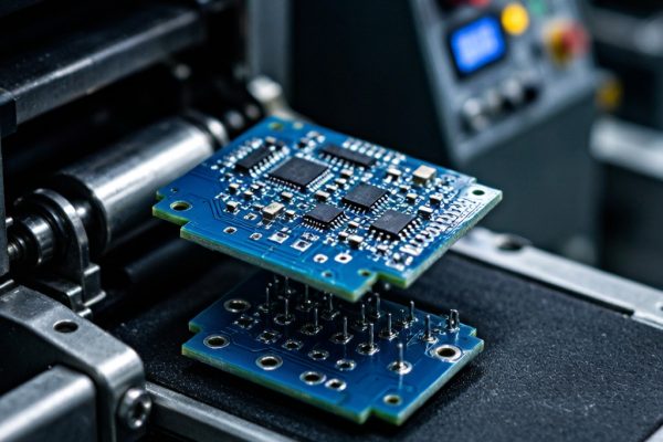
Modern SMT assemblies routinely combine components with vastly different thermal mass and reflow requirements on a single PCB. A typical smartphone motherboard, for instance, carries 0201 passives, QFN power management ICs, large BGA application processors, and co
ector shields—each with different peak temperature tolerances and wetting characteristics. A one-size-fits-all reflow profile is a recipe for inconsistent solder joint quality, with cold joints on large BGAs and overheated joints on small passives appearing on the same board.
This guide covers the practical engineering of reflow profiles for mixed component assemblies, with emphasis on the thermal profiling data that separates high-yield from marginal SMT production.
Understanding the Reflow Profile Zones
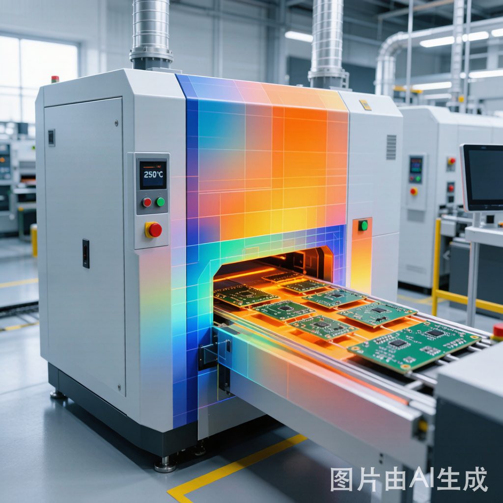
A convection reflow profile consists of four distinct thermal zones, each with specific process objectives:
1. Preheat Zone (ambient to ~150°C)
The preheat zone brings the entire assembly to a uniform temperature while driving off volatile solvents in the solder paste flux. For mixed component assemblies, the ramp rate is critical: too fast creates thermal gradients across the board that stress ceramic capacitors and large IC packages; too slow allows flux to dry out before activation. Target ramp rate: 1.5–3.0°C/second.
- Large BGAs and heavy copper planes absorb more heat, creating cold spots if ramp is too aggressive
- MLCCs are susceptible to thermal shock; military specifications limit ramp rate to 2°C/second maximum for ceramic capacitors ≥0603
- Moisture-sensitive packages benefit from a controlled ramp that allows water vapor to escape without cracking the mold compound
2. Soak Zone (150–200°C, 60–120 seconds)
The soak zone is the most critical for mixed assemblies because it equalizes temperature across components of different thermal mass. The flux activation chemicals volatilize and begin oxide reduction on the solderable surfaces. For boards with both tiny 0201 chips and 30 mm × 30 mm BGAs, soak time must be long enough for the BGA to catch up thermally without over-activating flux on the smaller parts.
| Assembly Type | Soak Time (150–200°C) | Soak Ramp |
|---|---|---|
| Lightweight board, small passives only | 60–90 seconds | 1.0–2.0°C/sec |
| Mixed passives + small ICs (SOIC, QFN) | 75–105 seconds | 0.8–1.5°C/sec |
| Mixed with large BGAs (>25 mm) | 90–120 seconds | 0.5–1.0°C/sec |
| Heavy copper (2 oz+), thick (>2.0 mm) PCB | 120–180 seconds | 0.3–0.8°C/sec |
3. Reflow Zone (above 217°C, 45–90 seconds TAL)
Time above liquidus (TAL) is the period when SAC305 solder is molten. The minimum TAL must be long enough for all joints to form proper intermetallic compound (IMC) layers; the maximum is limited by the thermal tolerance of the most heat-sensitive component. For mixed assemblies, the challenge is ensuring the largest BGA balls reach full liquidus while preventing small passives from exceeding their peak temperature tolerance.
- Peak temperature: 235–250°C for SAC305, with 245°C typical for mixed assemblies. Components rated 260°C peak provide adequate margin.
- TAL target: 60–75 seconds for most mixed assemblies; 60 seconds minimum for thick PCBs with heat sinks, 90 seconds maximum for assemblies with temperature-sensitive LEDs, polymer capacitors, or co
ectors
- Delta-T across board: Temperature difference between hottest and coldest component should not exceed 10°C at peak temperature
4. Cooling Zone (below 217°C to <100°C)
Controlled cooling is essential for fine-grained IMC formation and preventing thermal shock. Cooling rate of 2–4°C/second produces a uniform, fine-grained solder microstructure with optimal mechanical properties. Too-fast cooling creates brittle joints and risks thermal shock to ceramic capacitors; too-slow cooling produces coarse IMC grains with poor thermal cycling reliability.
Creating a Reflow Profile from Thermocouple Data
Modern reflow profiling uses wired thermocouples attached to representative components across the PCB. For a mixed assembly, attach at least four thermocouples:
- TC1: Smallest passive (e.g., 0201 or 0402) on an outer edge—fastest heating, earliest to reach peak temperature
- TC2: Largest BGA or QFN center—slowest heating, last to reach liquidus, thermal mass bottleneck
- TC3: Component on a ground/power plane area—large copper sinks heat, responds slowly
- TC4: PCB laminate between heavy copper areas—indicates bulk board temperature
The reflow oven zone temperatures and conveyor speed are adjusted iteratively until the profile meets specifications for all four thermocouples. The largest component dictates soak time and peak zone temperature; the smallest component dictates the maximum ramp rate and minimum cooling rate.
Common Profile Defects and Root Causes
| Defect | Root Cause | Profile Adjustment |
|---|---|---|
| Tombstoning (chip standing on end) | Uneven heating between two terminals; one pad reaches liquidus first | Extend soak time to equalize temperature; reduce ramp rate |
| Head-in-pillow (BGA) | Ball and paste not reaching liquidus simultaneously; paste solidifies before ball wets | Extend TAL; increase peak temperature 5°C; ensure BGA thermocouple confirms liquidus |
| Solder balling / solder beads | Excessive ramp rate before flux activation; spattering | Reduce preheat ramp to ≤3°C/sec; verify soak entry temperature |
| Voiding (>25% in BGA joints) | Flux volatiles trapped in molten solder; insufficient outgassing in soak | Extend soak time at 160–180°C; reduce ramp rate into reflow |
| Graping (grainy surface on solder joint) | Flux exhaustion before reflow; excessive time at elevated temperature | Shorten soak time or reduce soak temperature; ensure adequate flux volume |
| Cold joints / insufficient wetting | Component or pad not reaching liquidus; thermal inertia of large mass | Increase peak zone temperature; add top-side convection; extend TAL |
| Component cracking (MLCC) | Thermal shock from excessive ramp rate or cooling rate | Limit ramp to ≤2°C/sec; control cooling to 2–4°C/sec |
Profile Validation and Process Control
A validated reflow profile is a living document, not a one-time setup. Process control includes:
- Weekly profiling: Run a profile board through the oven to verify zone temperatures haven’t drifted
- Oven maintenance: Clean or replace convection fan filters monthly; verify thermocouple calibration quarterly
- Profile after maintenance: Any change to oven hardware (heater element, conveyor speed, fan replacement) requires re-profiling
- Documentation: Archive time-temperature profiles for each product, including thermocouple placement diagrams
Conclusion
Reflow profile optimization for mixed component assemblies is fundamentally a thermal engineering problem: delivering the right amount of heat to each component, at the right rate, so that every solder joint reaches liquidus under the same process window. Success depends on careful thermocouple placement, iterative oven zone tuning, and ongoing process validation. A well-optimized profile turns a board full of thermally mismatched components into a single, uniformly soldered assembly—and eliminates the most common root cause of SMT soldering defects.