## Introduction
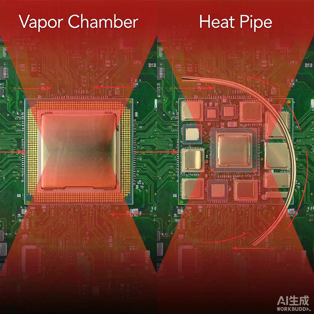
As processors, power stages, and RF modules shrink while power densities rise, PCB thermal management has become a design-limiting factor. Two phase-change technologies dominate the market: heat pipes and vapor chambers. Both use the latent heat of evaporation to move heat efficiently, but their geometries, thermal resistances, and best-use cases differ significantly.
Selecting the wrong solution can lead to hotspots, throttling, and premature failure. This article compares vapor chambers and heat pipes for PCB heat dissipation and provides a decision framework based on thermal resistance, spreading, orientation, and cost.
## How Heat Pipes Work
A heat pipe is a sealed tube containing a wick structure and a small amount of working fluid, typically water for electronics cooling. When one end is heated, the liquid evaporates, absorbs latent heat, and travels to the cooler end. There it condenses, releases heat, and the wick returns the liquid to the hot end by capillary action.
### Strengths
– Long-distance heat transport: Heat pipes can move heat 100–300 mm away from a source with minimal temperature drop.
– Flexibility: Tubes can be bent and flattened to fit tight enclosures.
– Orientation tolerance: Sintered copper wicks work against gravity over short distances.
### Weaknesses
– Limited spreading: A single heat pipe has a small cross-section and is poor at spreading heat laterally across a large area.
– Contact complexity: Multiple heat pipes are often needed, increasing assembly cost and thermal interface resistance.
## How Vapor Chambers Work
A vapor chamber is essentially a flattened heat pipe. It is a thin, sealed chamber — often 2–4 mm thick — with an internal wick and vapor space covering a large area. Heat enters at one or more hotspots, vapor spreads across the entire chamber, and condenses over the full surface, producing very uniform temperature distribution.
### Strengths
– Low spreading resistance: A vapor chamber can spread heat over a 100 x 100 mm area with thermal resistance lower than a solid copper plate of the same thickness.
– Thin profile: Modern vapor chambers are as thin as 2 mm, fitting inside smartphones, tablets, and compact power supplies.
– Multiple heat sources: A single chamber can cool several hotspots simultaneously.
### Weaknesses
– Higher cost: Vapor chambers are more expensive per watt of cooling than simple heat pipes.
– Limited transport distance: They are designed for spreading, not long-distance transport.
– Orientation sensitivity: Very thin chambers can suffer performance loss if operated against gravity for extended periods.
## Thermal Performance Comparison
### Thermal Resistance
Thermal resistance is the temperature rise per watt of heat flow. A typical 6 mm diameter heat pipe has a thermal resistance of 0.02–0.05 °C/W over 150 mm. A vapor chamber of 100 x 100 x 3 mm has a spreading thermal resistance of 0.01–0.03 °C/W across its surface.
For a single hotspot, a heat pipe that transports heat to a remote fin stack may perform well. For a large chip or multiple hotspots, a vapor chamber’s low spreading resistance usually wins.
### Spreading Resistance
Spreading resistance is the temperature gradient that appears when heat flows from a small source into a large heatsink. Solid copper has finite thermal conductivity, so the area directly above the source becomes hotter than the edges. Vapor chambers reduce this gradient by using phase change to distribute heat nearly isothermally.
For a 25 x 25 mm chip mounted on a 100 x 100 mm heatsink base, a vapor chamber can cut the spreading resistance by 30–50% compared to a solid copper base.
## Application Guidelines
### Choose Heat Pipes When
– Heat must be moved more than 100 mm from the source.
– The design already has a large fin stack or chassis wall available remotely.
– Cost is the primary constraint.
– The device orientation is fixed and favorable to gravity.
### Choose Vapor Chambers When
– The hotspot is large or there are multiple hotspots close together.
– The enclosure is thin and space is limited.
– Uniform temperature across the cooling surface is important.
– The product is a smartphone, laptop, base station, or compact power converter.
## Hybrid Solutions
Many high-performance designs combine both technologies. A vapor chamber spreads heat locally, and embedded heat pipes transport it to a remote fin stack. This approach is common in gaming laptops, telecom base stations, and EV onboard chargers where both spreading and transport are required.
## Conclusion
Vapor chambers and heat pipes are complementary rather than competing technologies. Heat pipes excel at moving heat over distance; vapor chambers excel at spreading heat over area. For PCB thermal management, the right choice depends on the heat source size, enclosure geometry, and whether the dominant problem is spreading resistance or remote heat transport. In many modern electronics designs, a hybrid of both delivers the best thermal performance.



