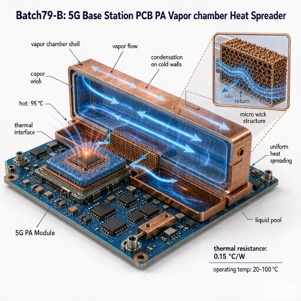
Introduction: Thermal Challenges in 5G Base Station Power Amplifiers
5G base stations transmit and receive signals across multiple frequency bands while handling wider cha
el bandwidths and more complex modulation schemes than previous generations. The power amplifiers (PAs) at the heart of these radios convert DC power to RF power, but much of that energy is lost as heat. In compact SMT packages such as Doherty amplifiers and massive MIMO modules, heat fluxes can exceed 50 W/cm², creating hot spots that threaten device reliability and output power.
Traditional solid metal heat spreaders and extruded aluminum heatsinks struggle to move heat away fast enough from these concentrated sources. Vapor chamber heat spreaders offer a passive, high-conductivity solution that spreads heat two-dimensionally across a large area before it reaches the fin stack. This article explains how vapor chambers work, why they suit 5G base station SMT power amplifiers, and how to integrate them effectively.
How Vapor Chambers Work
A vapor chamber is a sealed, flat copper enclosure partially filled with a working fluid, usually deionized water. The i
er walls are lined with a porous copper wick structure. When heat is applied at a hot spot, the working fluid evaporates, absorbing a large amount of latent heat. Vapor spreads rapidly through the chamber interior to cooler regions, where it condenses back to liquid and releases heat. The liquid returns to the hot zone through the wick by capillary action, completing the cycle.
This phase-change mechanism gives vapor chambers effective thermal conductivities far exceeding solid copper. While pure copper has a thermal conductivity of about 400 W/m·K, a well-designed vapor chamber can exhibit effective conductivities from 5,000 to 20,000 W/m·K in the plane. This allows a small heat source to be spread over a much larger area, reducing peak temperatures and smoothing thermal gradients.
Benefits for SMT Power Amplifiers
5G PA modules in SMT packages present several thermal management challenges. First, the heat source is small relative to the total board area. Second, multiple PAs may be placed close together, creating interacting hot zones. Third, base station enclosures are often sealed and exposed to tropical sunlight, raising ambient temperatures and limiting airflow.
Vapor chambers address these challenges by:
- Reducing hotspot temperature: Spreading heat lowers the peak junction temperature, improving PA efficiency and longevity.
- Enabling thi
er heatsinks:
Because heat is distributed across the entire base, thier fin stacks can be used without thermal penalty.
- Improving temperature uniformity: Uniform base temperature helps multiple PAs track similarly, reducing performance mismatch.
- Supporting passive cooling: In remote or noise-sensitive sites, vapor chambers allow larger passive heatsinks instead of fans.
Design Considerations
Effective vapor chamber integration requires attention to several design details. The chamber should be sized so that the heat source footprint covers no more than 10–20% of the spreading area. A ratio below this ensures vapor has room to spread and condense efficiently. Chamber thickness typically ranges from 2 mm to 4 mm for telecom applications, balancing thermal performance with mechanical rigidity.
The thermal interface material (TIM) between the SMT PA package and the vapor chamber must have low thermal resistance and remain stable under thermal cycling. Common choices include phase-change materials with thermal conductivities of 3–8 W/m·K, graphite sheets for lateral spreading, or soldered interfaces for the lowest resistance. The mounting force should be uniform to avoid bowing the chamber and creating air gaps.
Integration with PCB and Heatsink
In a typical 5G base station module, the SMT PA is soldered to a high-frequency PCB, often with thermal vias or a metal-backed substrate beneath the device. The vapor chamber sits above or below the PA, depending on whether the design uses topside or backside cooling. Topside cooling is more common because it provides a direct path from the package lid to the chamber.
The vapor chamber is then bonded or screwed to an aluminum fin stack. Fin density and height are chosen based on available airflow and acoustic limits. In tropical climates with low wind, larger fin pitches and natural convection designs may outperform dense fin arrays that require unreliable fan airflow.
Reliability and Qualification
Vapor chambers must survive thousands of thermal cycles, vibration, and shock during their service life. Qualification tests include thermal cycling from -40 °C to 85 °C or higher, mechanical shock, random vibration, and accelerated life testing. Hermetic sealing is essential; any leak causes the chamber to dry out and lose performance. Manufacturers typically guarantee 10 or more years of life for telecom-grade chambers.
Cost and Performance Trade-offs
Vapor chambers cost more than solid copper or aluminum spreaders, but the system-level savings can be significant. Because a vapor chamber enables thi
er, lighter heatsinks and reduces fan requirements, the total thermal solution may be smaller and less expensive than a conventional design. In high-volume 5G base station production, the incremental cost of a vapor chamber is often justified by improved reliability, higher output power, and reduced field failures.
Conclusion
Vapor chamber heat spreaders are a proven thermal management technology for 5G base station SMT power amplifiers. By exploiting phase-change heat transfer, they spread concentrated heat efficiently, reduce peak temperatures, and enable compact, reliable designs for tropical and urban deployments. Proper sizing, TIM selection, and mechanical integration are the keys to realizing their full benefit.



