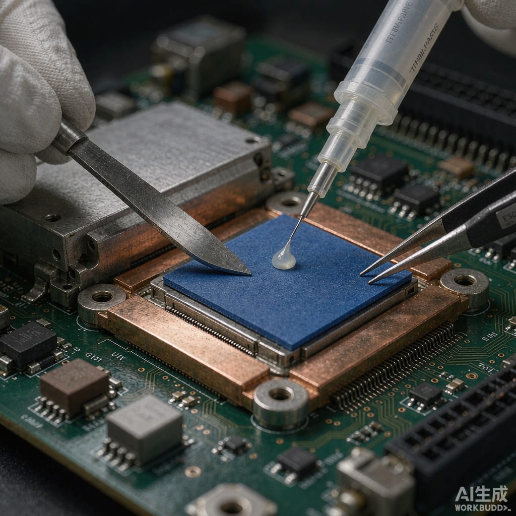
## Why Thermal Interface Materials Matter
In modern power electronics, the thermal interface between a heat-generating component (CPU, GPU, power MOSFET, LED) and its heatsink is often the largest thermal bottleneck in the entire heat dissipation path. Even a perfectly machined heatsink base has microscopic surface irregularities that trap air gaps when pressed against a component. Air is a poor thermal conductor (0.026 W/m·K), and even a thin air layer can increase thermal resistance dramatically.
Thermal interface materials (TIMs) fill these microscopic gaps, replacing air with a material that has 10–100× better thermal conductivity. Selecting the right TIM is critical for achieving target junction temperatures and ensuring long-term reliability.
## Categories of Thermal Interface Materials
### 1. Thermal Greases
Thermal greases are silicone or non-silicone oil bases loaded with thermally conductive fillers (alumina, zinc oxide, boron nitride, or silver).
Key properties:
– Thermal conductivity: 1.0–8.5 W/m·K
– Thermal resistance: 0.05–0.20 °C·cm²/W (at 50 µm bond line)
– Application: Manual or screen-printed
– Cost: Low to moderate ($3–15 per gram)
Advantages:
– Excellent wetting of both surfaces
– Conformable to irregular surfaces
– Very thin bond lines possible (25–75 µm)
Disadvantages:
– Pump-out during thermal cycling (oil migration under repeated expansion/contraction)
– Dry-out over time (silicone oil volatility)
– Messy application process
– Not reworkable without solvent cleaning
Thermal greases are best for high-volume production lines with automated dispensing where thin bond lines are critical, and for consumer electronics with moderate power density.
### 2. Thermal Pads (Silicone/Non-Silicone)
Pre-cured thermal pads are solid elastomeric sheets loaded with thermally conductive fillers.
Key properties:
– Thermal conductivity: 1.0–6.0 W/m·K
– Thickness: 0.25–5.0 mm (commonly 0.5–2.0 mm)
– Hardness: 30–80 Shore OO
– Cost: $0.50–3.00 per pad
Advantages:
– Clean, fast application (pick-and-place compatible)
– No pump-out or dry-out
– Good gap-filling for tolerance stack-up
– Reusable during rework
Disadvantages:
– Higher thermal resistance than grease due to thicker bond line
– Compressibility limits — may not fully conform at low clamping pressure
– Limited to gap-filling applications, not optimal for very thin interfaces
Thermal pads are the standard choice for medium-power applications (5–50 W) where ease of assembly and reworkability matter more than absolute minimum thermal resistance.
### 3. Phase-Change Thermal Pads
Phase-change pads combine the clean handling of solid pads with the wetting performance of greases. At room temperature, they are solid and easy to handle. At operating temperature (50–60°C), they soften and flow to fill microscopic surface irregularities.
Key properties:
– Thermal conductivity: 2.0–8.0 W/m·K
– Bond line after flow: 25–50 µm
– Phase-change temperature: 50–60°C
– Cost: $0.80–4.00 per pad
Advantages:
– Very low thermal resistance after initial heat cycle
– No pump-out (solid at room temperature, limited migration at operating temperature)
– Clean application
– Good for high-power applications requiring thin bond lines
Disadvantages:
– Requires one thermal cycle (heat-up/cool-down) before reaching optimal performance
– Surface preparation still required for best results
Phase-change pads are ideal for high-power CPU/GPU applications (50–200 W) where automated assembly and minimum thermal resistance are both required.
### 4. Thermal Gap Fillers
Gap fillers are ultra-soft, heavily loaded silicone compounds that cure in place after dispensing. They are designed to fill large, irregular gaps (1–10 mm) between components and heatsinks or housings.
Key properties:
– Thermal conductivity: 1.5–6.0 W/m·K
– Gap range: 0.5–10 mm
– Curing: Room temperature vulcanization (RTV), 4–24 hours
– Cost: $0.20–1.50 per gram dispensed
Advantages:
– Excellent for irregular geometries and variable gaps
– Very low hardness after cure (10–30 Shore OO) — minimal stress on components
– Can bridge component height variations on a PCB
Disadvantages:
– Long cure time delays further assembly steps
– Non-reworkable (must be scraped off for rework)
– Dispensing requires precision equipment
Gap fillers are the preferred solution for multi-component boards where individual components have different heights, and for applications where the heatsink-to-PCB gap varies across the board.
### 5. Thermal Adhesives
Thermal adhesives combine gap-filling properties with structural bonding, eliminating the need for mechanical clamping hardware.
Key properties:
– Thermal conductivity: 1.0–3.5 W/m·K
– Bond strength: 1–10 MPa
– Cure: Room temperature or heat-accelerated
– Cost: $1.50–8.00 per gram
Advantages:
– Eliminates mechanical fasteners
– Provides thermal transfer and structural bonding simultaneously
– Good for small components where clamping is impractical
Disadvantages:
– Lower thermal conductivity than dedicated TIMs
– Non-reworkable without significant effort
– Bond strength may degrade at high operating temperatures
## Selection Methodology
### Step 1: Calculate Required Thermal Resistance
Using the component’s maximum junction temperature (Tj_max), maximum ambient temperature (Ta_max), and power dissipation (P):
R_thermal_total = (Tj_max – Ta_max) / P
Subtract the heatsink thermal resistance and component package thermal resistance to obtain the maximum allowable TIM thermal resistance. This is your selection target.
### Step 2: Determine Gap Geometry
Measure the actual gap between the component and heatsink across the expected tolerance range. This determines whether you need a thin-interface material (grease, phase-change pad) or a gap-filling material.
### Step 3: Evaluate Operating Conditions
– Maximum operating temperature: Must be within TIM stability range
– Thermal cycling range: Pump-out risk for greases increases with large ΔT
– Expected service life: Long-life applications (7–10 years) favor solid pads over greases
– Rework frequency: Frequent rework favors pads and phase-change materials
### Step 4: Compare Cost-Performance Ratio
For a 100 W application requiring R_TIM < 0.15 °C/W at a 25 mm × 25 mm interface area:
| TIM Type | Conductivity (W/m·K) | Thickness (mm) | R_TIM (°C/W) | Cost per Unit |
|—|—|—|—|—|
| Premium grease (Ag-filled) | 8.5 | 0.05 | 0.002 | $8.00 |
| Phase-change pad | 6.0 | 0.05 | 0.003 | $3.50 |
| Thermal pad (high-end) | 4.0 | 0.50 | 0.050 | $2.00 |
| Gap filler | 3.0 | 2.00 | 0.267 | $0.80 |
Note: The thermal resistance values assume a 625 mm² contact area. Actual performance depends on contact pressure and surface flatness.
## Application Best Practices
### Surface Preparation
Both the component surface and heatsink base should be cleaned with isopropyl alcohol before TIM application. Surface flatness should be verified — if either surface has more than 0.05 mm flatness deviation across the contact area, a gap-filling material is required rather than a thin grease.
### Clamping Pressure
Most TIMs require a clamping pressure of 50–200 kPa to achieve optimal bond line thickness. Insufficient pressure leaves thick bond lines and high thermal resistance; excessive pressure can damage components or cause the TIM to be squeezed out.
### Reapplication Intervals
For thermal greases in high-temperature applications, consider reapplication every 3–5 years. Phase-change pads and solid pads generally do not require maintenance during the product lifetime.
## Conclusion
Selecting the optimal thermal interface material requires understanding the gap geometry, power density, operating temperature range, and rework requirements of the specific application. For thin interfaces and high power density, phase-change pads or premium greases deliver the best performance. For variable gaps and ease of assembly, thermal pads and gap fillers are the practical choice. For sourcing TIMs and thermal management solutions, contact TechMartSE for product specifications and technical support.



