## Introduction
In surface-mount technology (SMT) assembly, the quality of the copper strip used for leadframes, bus bars, and shielding frames is often judged by alloy temper, thickness tolerance, and surface finish. Yet one parameter that process engineers frequently underestimate is the edge condition produced during slitting. Burr height, edge squareness, and work-hardened zones at the slit edge directly influence solder paste transfer efficiency, stencil-to-substrate gasket sealing, and ultimately first-pass yield (FPY) on fine-pitch printing lines.
This article examines how slitting parameters — blade clearance, overlap, and cutting speed — interact with copper temper to produce edge defects, and how those defects propagate into solder paste printing defects on SMT production lines.
## The Slitting Process and Edge Defect Formation
### Blade Clearance and Burr Mechanics
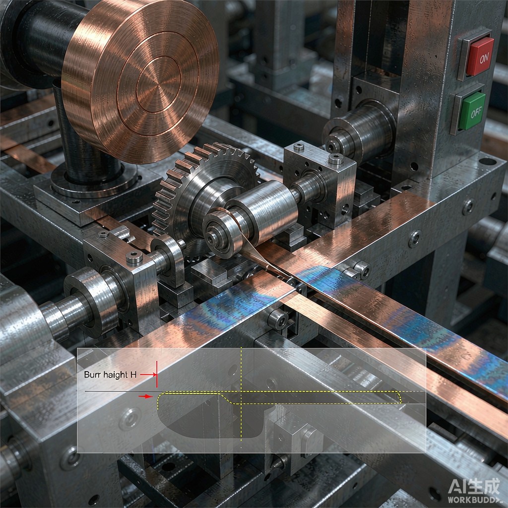
Precision copper strip for SMT applications is typically slit from wider master coils using rotary shear or multi-knife slitting lines. The cutting action involves two rotating disc blades with a precisely set side clearance and overlap. When the blades are too far apart, the copper tears rather than shears, producing a heavy rollover burr on the bottom edge. When the clearance is too tight, the blades rub aggressively, generating frictional heat that work-hardens the edge and can produce micro-cracks.
For C19400 (CuFe2P) and C26000 (cartridge brass) strip at 0.10–0.30 mm thickness, the optimal blade side clearance is typically 8–12% of the strip thickness. At this setting, burr height can be held below 10 micrometers. A burr exceeding 25 micrometers is problematic because it acts as a physical dam during solder paste printing, trapping paste at the aperture edge and causing inconsistent deposition volume.
### Edge Squareness and Its Impact on Gasket Sealing
Edge squareness — the deviation of the slit edge from a true 90-degree angle relative to the strip surface — is another critical metric. For SMT leadframe applications, edge squareness should be within 2 degrees of perpendicular. When the edge is rolled or feathered, the strip does not seat flat against the stencil underside during paste printing, creating a gap through which paste can bleed.
This is particularly relevant for embedded copper strips used as heat spreaders within printed circuit board (PCB) laminates. If the strip edge is not square, the adhesive bond line thickness varies, creating thermal resistance hotspots and potential delamination sites during reflow.
## Measuring Edge Quality: Burr Height, Rollover, and Work Hardening
### Burr Height Measurement
Burr height is measured using optical profilometry or micrometer-based edge gauges. The target for SMT-grade copper strip is a burr height of 10 micrometers or less. Some ultra-precision applications, such as 0.2 mm pitch leadframes, demand burr heights below 5 micrometers.
### Rollover and fracture zone
When the slitting blade shears the copper, three zones form at the edge: the rollover zone (plastic deformation where the copper bends downward), the burnish zone (clean shear), and the fracture zone (tensile failure). An ideal slit edge has minimal rollover (less than 10% of thickness) and a burnish zone covering 30–40% of the thickness. A fracture zone that is too large indicates excessive blade clearance; a burnish zone that is too large indicates insufficient clearance.
### Work Hardening at the Edge
The shearing action work-hardens the copper at the edge to a depth of 50–150 micrometers. For half-hard temper strip (H02, approximately 1/2 hard), the Vickers hardness at the edge can increase from a bulk 110–130 HV to 160–180 HV. This localized hardening affects downstream forming operations — if the strip is subsequently bent or stamped, the hardened edge is prone to cracking.
## Impact on Solder Paste Printing Performance
### Paste Transfer Efficiency
Solder paste transfer efficiency — the ratio of paste volume deposited to the aperture volume — is the key metric for paste printing quality. In fine-pitch applications (0.4 mm pitch and below), transfer efficiency targets are 80% or higher with low variation (coefficient of variation under 10%).
When copper strip with excessive burr is used as a substrate or leadframe beneath or adjacent to the stencil, the burr creates localized gaps between the stencil and substrate. Solder paste flows into these gaps during the squeegee stroke, producing paste bridges, insufficient deposits, or solder balls after reflow.
### Stencil Gasket Integrity
For step stencils and nano-coated stencils used in SMT printing, the gasket seal between the stencil underside and the substrate is critical. A copper strip edge with a 30 micrometer burr can lift the stencil locally by that amount, breaking the gasket seal over a width of several hundred micrometers. In production, this manifests as inconsistent paste volumes at aperture locations near the copper strip edge.
## Slitting Parameter Optimization
### Blade Selection and Geometry
For copper strip slitting, the blade material is typically D2 tool steel or tungsten carbide. Carbide blades maintain edge sharpness longer (3–5 times the blade life of D2) but are more brittle and sensitive to misalignment. The blade edge radius should be maintained below 5 micrometers through regular dressing.
### Speed and Tension Control
Slitting speed for SMT-grade copper strip ranges from 30 to 120 meters per minute. Higher speeds improve throughput but increase frictional heating, which can soften temper and increase burr formation. A practical compromise is 60–80 m/min with active blade cooling via compressed air.
Strip tension during slitting must be controlled to prevent edge waviness. The recommended tension is 50–70% of the strip yield strength, adjusted for width and thickness. Excessive tension causes edge elongation and camber; insufficient tension allows the strip to wander between blades.
## Best Practices for SMT Copper Strip Procurement
### Specification Sheet Recommendations
When procuring copper strip for SMT applications, specify the following edge quality parameters:
– Maximum burr height: 10 micrometers (5 micrometers for ultra-fine pitch)
– Edge squareness: within 2 degrees of perpendicular
– Camber: less than 1 mm per meter
– Surface roughness (Ra): 0.2–0.4 micrometers on both surfaces
– Temper: H02 (half-hard) or H04 (hard) per ASTM B465
### Incoming Inspection Protocol
Implement an incoming inspection protocol that samples the first and last meter of each coil for burr height and edge squareness. Use optical profilometry for burr measurement and a precision square for edge angle verification. Reject coils where burr height exceeds specification on more than 10% of sampled measurements.
## Conclusion
Edge quality from slitting is a first-order parameter for SMT copper strip performance, directly affecting solder paste transfer efficiency and first-pass yield. By controlling blade clearance, speed, and tension during slitting, and by specifying burr height and edge squareness in procurement documents, electronics manufacturers can eliminate a significant source of printing defects. For SMT production lines ru
ing fine-pitch components, this attention to edge quality translates directly into higher yield and lower rework costs.



