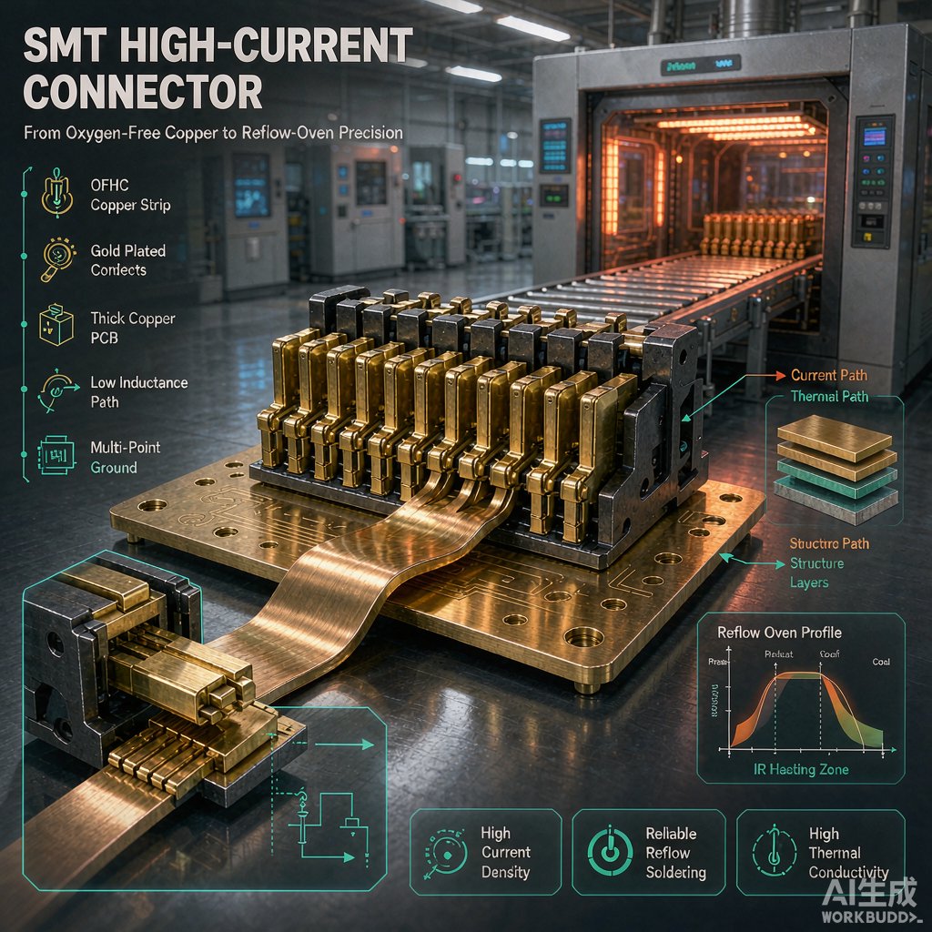
Why OFHC Copper Strip Matters in SMT Power Co
ectors
Surface-mount technology (SMT) power co
ectors and busbars must carry increasingly high current in compact footprints. The conductor material directly determines contact resistance, temperature rise, and long-term reliability. Among the available copper alloys, oxygen-free high-conductivity (OFHC) copper strip, commonly designated C10200, is the material of choice for engineers who need maximum electrical and thermal performance.
Unlike standard electrolytic tough pitch (ETP) copper, OFHC copper contains less than 5 ppm oxygen. The absence of copper oxide inclusions gives it higher electrical conductivity—typically 101% IACS in the a
ealed condition—and better performance during thermal cycling. For SMT high-current co
ectors, this translates into lower I²R losses and reduced risk of solder-joint degradation.
Key Properties of C10200 Copper Strip
Electrical and Thermal Conductivity
OFHC copper strip offers electrical conductivity of 100–102% IACS and thermal conductivity around 390 W/(m·K). These values are superior to ETP copper and significantly better than brass or bronze alternatives. In high-current SMT co
ectors, every fraction of a percent improvement in conductivity reduces resistive heating and allows smaller conductor cross-sections.
Softening and A
ealing Behavior
One concern with any copper strip used in SMT assemblies is the reflow profile. Peak temperatures of 245–260°C during lead-free reflow can partially a
eal cold-worked strip. OFHC copper softens more predictably than ETP copper because oxygen-related precipitation is absent. Design teams often specify a half-hard (H02) or quarter-hard (H01) temper to retain spring force in contact beams while still accepting the reflow cycle.
Outgassing and Vacuum Compatibility
Because OFHC copper has very low volatile content, it is widely used in vacuum and hermetic applications. For co
ectors sealed inside outdoor enclosures, aerospace modules, or photonics packages, this low-outgassing characteristic reduces contamination risk on optical or RF surfaces.
Design Guidelines for SMT High-Current Co
ectors
Strip Thickness and Current Carrying Capacity
For SMT busbars and blade contacts, common strip thicknesses range from 0.20 mm to 0.80 mm. A 0.50 mm thick C10200 strip at 30°C temperature rise can typically carry 15–25 A depending on trace width and copper weight. Designers should cross-check against IPC-2221 or perform finite-element thermal simulation when currents exceed 20 A.
Plating Compatibility
Raw OFHC copper oxidizes quickly in air, so strip contacts are usually plated. A typical stack is 1.25–2.5 µm nickel underplate followed by 0.8–1.5 µm pure gold for low-contact-resistance mating surfaces. For cost-sensitive applications, tin or tin-lead plating over nickel provides acceptable solderability and corrosion protection, although insertion wear is higher.
Formability and Stress Relaxation
High-current SMT co
ectors often rely on formed contact beams that generate normal force. OFHC copper in H02 temper offers a good balance between yield strength (205–250 MPa) and bendability. After forming, a stress-relief a
eal at 150–200°C can reduce residual stress and improve resistance to stress relaxation at elevated operating temperatures.
Quality Checks and Supplier Qualification
When sourcing OFHC copper strip for SMT co
ectors, request mill test certificates confirming ASTM B170 or ASTM B152 compliance. Verify oxygen content by inert-gas fusion analysis and check that surface roughness Ra is below 0.8 µm if fine-pitch plating is required. Flatness and edge burr control are critical for automated pick-and-place; camber should be less than 1 mm per 300 mm length.
Conclusion
OFHC copper strip delivers the conductivity, thermal performance, and reflow stability that high-current SMT co
ectors need. By specifying the right temper, plating system, and dimensional tolerances, design teams can achieve reliable power interco
ects in compact, thermally challenging assemblies.



