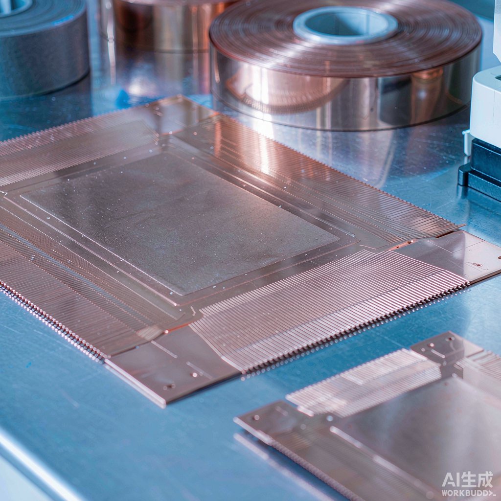
Every molded SMT package — from a SOT-23 transistor to a QFP microcontroller — rests on a copper skeleton that nobody sees after molding: the lead frame. It carries the die, provides the bond pads for wire bonding, forms the external leads that solder onto the PCB, and drains heat out of the package. Choosing the right lead frame copper strip is therefore a packaging decision, not just a purchasing one. This guide walks through alloy selection, mechanical requirements, stamping considerations, and plating systems for SMT lead frames.
Why Copper Dominates Lead Frame Manufacturing
Lead frames were historically stamped from Alloy 42 (Fe-42Ni), which offered a coefficient of thermal expansion (CTE) closely matched to silicon. Copper replaced it in most SMT applications for three reasons:
- Thermal conductivity: Copper alloys conduct 150–400 W/m·K versus roughly 10 W/m·K for Alloy 42, dramatically lowering the thermal resistance of the package and letting heat spread into the PCB.
- Electrical conductivity: Copper runs 20–95% IACS depending on alloy, reducing the resistance of power leads in discretes and power QFNs.
- Cost and formability: Copper strip is cheaper per functional part and stamps faster with longer die life at fine pitches.
The trade-off is CTE mismatch: silicon expands at about 2.6 ppm/°C while copper expands at 16–17 ppm/°C. This mismatch drives die-attach and wire-bond fatigue in large-die packages, which is why die-attach layer design and copper thickness must be engineered together with the alloy.
Common Lead Frame Copper Alloys
C11000 (ETP Copper)
Electrolytic tough pitch copper, ~100% IACS, excellent for die paddles and thermal reliefs where forming demand is low. Its main weakness is softening resistance: it a
eals at moderate temperatures, so tie bars and paddles can deform during molding operations if the temper is not chosen carefully.
C19400 (Cu-Fe-P)
The workhorse of lead frame alloys. Iron and phosphorus additions sacrifice a little conductivity (~65% IACS) in exchange for substantially higher strength and softening resistance. Typical applications include SOIC, QFP, and discrete packages where leads must survive lead-forming and board-level bending.
C19700 (Cu-Fe-P-Mg)
A higher-strength variant retaining ~80% IACS. It offers an excellent combination of conductivity and stress relaxation resistance at 150 °C, making it the default choice for power discretes, copper-clip packages, and any frame exposed to automotive AEC-Q qualification.
C15100 / C15000 (Cu-Zr, Cu-Zr-Mg)
Zirconium-bearing coppers retain over 85% IACS with fine softening resistance. They are favored where both high current capacity and repeated 150–175 °C thermal excursions occur, such as IGBT module bases and MOSFET TO-leadframes.
Mechanical Requirements for SMT Reliability
Bend Formability
External leads are bent at 90° during lead forming. The critical spec is minimum bend radius expressed as R/t (radius over thickness). Good lead frame alloys achieve 90° bends at R/t ≤ 1 in the transverse direction at half-hard temper. Buying strip too soft saves forming energy but compromises tie-bar stiffness; too hard and bends crack the plating or the substrate.
Stress Relaxation
Leads pressed against a PCB or contact spring lose clamping force over time at temperature. Specify stress relaxation data at the package’s actual operating temperature — typically 125–150 °C for automotive — rather than room-temperature yield strength. C19700-class alloys retain roughly 80% of initial stress after 1,000 hours at 150 °C, while plain C11000 can fall below 50%.
Softening Resistance
Frames experience molding compound cure at 175 °C and die bonding well above that. The alloy must resist recrystallization so that paddle flatness and tie-bar integrity survive processing. Mill certificates should include post-aging hardness or conductivity checks.
Stamping versus Etching
Production lead frames are progressively stamped. Etching is reserved for prototypes and exotic geometries because it is slower and generates chemical waste, but it avoids burrs entirely and can produce internal cavities dies ca
ot.
Edge Quality and Burr Control
Stamped edges have a burnish zone, fracture zone, and possible burr. For frames that will be molded, a burr height below 8–10% of strip thickness is the usual acceptance limit; exposed-lead QFN packages demand tighter control because burrs become the molded lead surface. Key controls:
- Die clearance of 5–10% of material thickness per side, tuned to the alloy’s shear strength.
- Sharp tooling maintenance schedules — burr height grows predictably with die wear, so logging it catches drift before scrap.
- Strip temper chosen so the shear zone is clean rather than tearing.
Plating Systems on Lead Frames
Bare copper oxidizes fast enough to ruin wire bonding and solderability, so frames are plated before or after stamping:
- Nickel barrier, 1–3 µm: Prevents copper diffusion into tin or silver topside layers and stabilizes contact resistance.
- Tin or matte tin, 2–5 µm: The solderable finish for most SMT leads; matte tin is preferred to reduce whisker risk on pure tin systems.
- Silver spot plating, 1–3 µm: Applied locally on die pads and wire-bond fingers where bondability and thermal cycling performance matter.
- Palladium or PdNi finishes: Whisker-immune alternatives for high-reliability and fine-pitch applications.
Selective plating — plating only the tips and bond areas — cuts precious metal cost dramatically on high-volume discrete frames.
Incoming Quality Checks
A practical incoming inspection plan for lead frame strip covers: thickness and camber across the coil, tensile strength and elongation against certificate values, conductivity (%IACS) as a fast alloy-identity check, grain size on a cross-section, and bend tests at the specified R/t. For high-reliability programs, add stress relaxation coupons and plating adhesion tape tests.
Conclusion
Lead frame selection is a system decision: the alloy sets the conductivity–strength–relaxation triangle, the temper and edge quality decide how well it stamps, and the plating stack protects bondability through reflow. For most SMT work, C19400 covers standard logic and analog packages, C19700 takes power and automotive duty, and C11000 remains the economical choice for thermal paddles. Specify stress relaxation and softening resistance explicitly in the purchase spec — those are the properties that decide whether the frame still behaves like a spring after five years at 150 °C.



