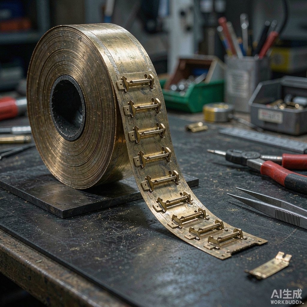
Automotive ECUs, 5G base station boards, and industrial controls pack SMT co
ectors that must hold reliable contact force for 10–15 years, often inside enclosures that reach 85–125 °C. Standard copper alloys lose spring force at these temperatures, and a co
ector that tests fine at room temperature can fail in the field when contact normal force drops below the threshold for stable resistance. CuNiSi copper strip — the copper-nickel-silicon family that includes UNS C7025 — was developed for exactly this duty. For designers specifying SMT co
ector contacts in high-reliability equipment, understanding stress relaxation behavior is as important as conductivity or cost.
Why Contact Force Fades Over Time
A stamped co
ector contact is a cantilever spring held at a permanent deflection inside the housing. The contact force that wipes oxides off mating surfaces and stabilizes resistance comes from elastic stress in the strip. At elevated temperature, that stress slowly converts to plastic deformation — a phenomenon called stress relaxation. The alloy does not need to yield visibly; even a few percent of stress loss shifts contact resistance upward and widens the margin for intermittent faults.
How Relaxation Is Specified
Suppliers characterize relaxation by holding a bent sample at temperature — commonly 150 °C, 200 °C, or 250 °C — for 1,000 hours and reporting the percentage of initial stress retained. Phosphor bronze C5191 typically retains 60–70% of stress after 1,000 hours at 150 °C, while properly aged CuNiSi retains 85–90% under the same conditions. At 200 °C the gap widens further. This single data point often decides material selection for automotive and telecom sockets.
The CuNiSi Advantage: Precipitation Hardening
CuNiSi alloys combine roughly 1–3% nickel with 0.4–1.0% silicon. During solution treatment and subsequent age hardening, nickel and silicon form fine Ni2Si precipitates that pin dislocations and raise strength without the heavy cold work that hurts formability. The result is a rare combination:
• Electrical conductivity of 40–55% IACS — several times higher than phosphor bronze (about 12–20%)
• Yield strength above 700 MPa in hard tempers, comparable to beryllium copper at a fraction of the cost
• Excellent resistance to stress relaxation up to 150–200 °C
• No beryllium content, simplifying environmental compliance and machining dust management
Comparing the Spring-Alloy Shortlist
Phosphor bronze remains the economic default for consumer co
ectors and performs well below 105 °C. Beryllium copper C17200 offers the best strength and relaxation resistance but carries cost and handling constraints. CuNiSi occupies the middle ground: performance approaching C17200 at conductivity and price levels closer to phosphor bronze. For contacts carrying both signal and power — battery holders, busbar fingers, memory slots — CuNiSi is frequently the most balanced choice.
Strip Processing and Temper Selection
Mills deliver CuNiSi strip in tempers from TM01 to TM08 (or equivalent quarter-hard to spring designations). Higher tempers increase yield strength through cold rolling, but every increment reduces bend formability. A practical selection approach starts from the forming plan rather than the datasheet.
Matching Temper to the Forming Plan
Contacts bent in the transverse direction tolerate harder tempers than those bent along the rolling direction. Where a contact requires a sharp 90-degree bend in a thin section, specify a temper with a guaranteed 90-degree bend capability — often the 1/2-hard to 3/4-hard range — and rely on age hardening, rather than cold work, for final strength. Review bend-axis allowances with the mill before locking tooling designs, because temper selection made after tooling is usually the cause of bend cracking claims.
Stamping and Assembly Considerations
CuNiSi strip runs well on progressive dies at speeds similar to phosphor bronze. A few production details deserve attention:
• Keep die clearances around 5–8% of strip thickness to minimize burr height on contact beams
• Deburr or add radii at bend lines on the outer tension surface to avoid fatigue initiation
• Plan plating after forming: tin or nickel plates cleanly over CuNiSi, while plating before heavy forming risks cracking the deposit on tight bends
Plating and the Contact Interface
Most SMT co
ector designs specify selective tin at 2–4 µm over a 1–2 µm nickel barrier, or gold flash over nickel for low-force, low-voltage signal contacts. The copper-nickel-silicon substrate’s low surface diffusion keeps plating adhesion stable through reflow and thermal cycling, which matters for packages that see multiple soldering passes.
Thickness and Design Guidelines
Typical strip gauges run 0.08–0.40 mm. Contact force scales with beam thickness cubed, so small thickness changes dominate spring calculations — verify spring-rate models against actual strip yield values from the mill certificate rather than nominal datasheets. For SMT solder tails, control camber and edge burr so coplanarity stays within 0.05 mm across the strip width during progressive die feeding; out-of-plane strips cause the classic partially-soldered tail defect after reflow.
Choosing a Supplier
When evaluating CuNiSi strip sources, request relaxation test data at your actual service temperature, mill certificates with yield and conductivity values per coil, and bend-test guarantees for the specified temper. Lot-to-lot consistency matters more than a headline datasheet number, because co
ector force tolerances are tight. Sourcing strip with verified relaxation data ensures the co
ector engineered today still meets contact-resistance targets after a decade inside a hot enclosure.



