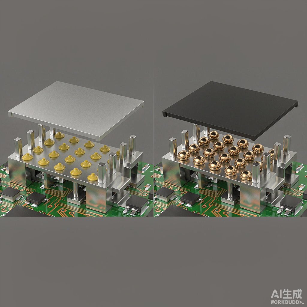
Two Attachment Methods, Two Engineering Trade-offs
Board-level EMI shield cans protect sensitive analog and RF circuits from coupling and external radiation. Once the shield fence and cover are placed, the question becomes: how do you reliably attach the cover to the fence? Two methods dominate modern SMT lines—conductive adhesive bonding and solder attachment. Each offers distinct advantages in electrical performance, manufacturability, rework, and cost.
This article compares the two approaches head-to-head, with practical guidance for choosing the right method based on product requirements.
Conductive Adhesive Attachment
How It Works
Conductive adhesives are typically silver-filled epoxy or silicone pastes that cure at temperatures between 80 and 150 degrees Celsius. The shield cover is dispensed with adhesive dots or pre-coated with pressure-sensitive adhesive, then placed on the fence and cured in an inline oven or during the second-side reflow of double-sided boards.
Electrical Performance
Modern silver-filled adhesives deliver volume resistivity between 1×10⁻⁴ and 5×10⁻⁴ ohm·cm, providing effective RF bonding up to several GHz. Contact resistance at the joint is usually below 5 milliohms. For 5G sub-6 and mmWave applications, however, shielding effectiveness above 30 GHz can degrade if the adhesive layer is too thick or uneven.
Process Advantages
Conductive adhesives cure at low temperatures, so they are ideal for temperature-sensitive components or double-sided assemblies where the second side ca
ot be reflowed. They also tolerate larger dimensional variation and surface roughness, which simplifies fixture design and reduces tooling cost.
Limitations
Adhesives ca
ot match the thermal and electrical stability of a true metallurgical solder joint. They have lower current-carrying capacity and may degrade in high-temperature automotive environments. Rework is difficult: heating the adhesive above its cure temperature softens it but rarely returns it to flowable state, often forcing shield destruction.
Solder Attachment
Reflow and Selective Soldering
Solder-attached shields use tin, tin-silver, or tin-lead plating on the fence flange and cover. The cover is placed after SMT components, and the joint is formed either by full reflow, by selective soldering, or by laser soldering. Solder provides both mechanical strength and a true metallurgical bond across the seam.
Electrical and Thermal Performance
Solder joints deliver contact resistance below 1 milliohm and stable performance from DC to millimeter-wave frequencies. Thermal conductivity is also higher, allowing the shield to act as a heat spreader for nearby components. This is especially valuable in automotive and power-electronics modules.
Process Considerations
Solder attachment requires precise paste printing or preform placement on the fence flange. Voids in the solder joint create gaps that leak RF energy, so X-ray inspection is recommended for high-frequency designs. Pad design must include adequate solder volume, typically a 0.1 to 0.15 mm stencil thickness.
Rework and Field Service
Solder joints can be desoldered with hot air, allowing cover removal for component rework. This significantly reduces service cost on complex assemblies. However, repeated reflow cycles can degrade the metallization on the fence flange, eventually limiting repair cycles.
Side-by-Side Comparison
Shielding Effectiveness
For frequencies below 6 GHz, both methods provide comparable shielding above 60 dB when seams are continuous. Above 24 GHz, solder attachment maintains more stable performance because of its uniform metallurgical bond. Conductive adhesive can show 5 to 10 dB degradation at mmWave if adhesive thickness exceeds 50 microns.
Thermal Cycling Reliability
Solder joints handle -40 to +125 degree Celsius thermal cycling for more than 1000 cycles with proper plating. Conductive adhesives can survive similar cycling but lose electrical contact faster if cured below 125 degrees Celsius or if the substrate CTE mismatch is large.
Cost and Throughput
Conductive adhesive eliminates solder printing, stencil cleaning, and post-reflow inspection, reducing direct material cost by 20 to 40 percent. However, adhesive cure time adds 30 to 60 minutes to batch ovens or requires extra in-line oven length. Solder attachment is faster in volume but requires precision paste printing.
Rework and Service
Solder is clearly superior for rework. Adhesives essentially force shield destruction, increasing service cost for any board that returns for component replacement.
Selection Guidance
Use conductive adhesive when:
- Components ca
ot survive full reflow temperatures
- Double-sided assembly makes second reflow impossible
- Cost dominates and minimal rework is expected
- Operating frequency stays below 6 GHz
Use solder attachment when:
- Operating frequency includes mmWave bands above 24 GHz
- Highest thermal and electrical stability is required
- Automotive or industrial environments demand long-term reliability
- Field serviceability and rework are part of the product lifecycle
Both methods can coexist on the same board: solder the most critical RF shields while using adhesive for digital or low-frequency compartments. With proper process control, board-level EMI shields provide decades of reliable protection across consumer, automotive, and industrial products.



