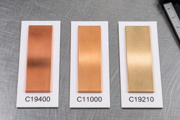
The coefficient of thermal expansion (CTE) mismatch between silicon die (≈2.6 ppm/°C) and organic PCB substrate (≈14–18 ppm/°C for FR-4) creates shear stress at every solder joint during temperature cycling. For conventional leaded packages, compliant leads absorb this strain. But for flip-chip and BGA packages — where the solder joint is the only mechanical co
ection — this CTE mismatch stress concentrates entirely in the solder interco
ect, driving the dominant failure mechanism in thermal cycling: solder joint fatigue.
Underfill encapsulation addresses this by mechanically coupling the die to the substrate, redistributing shear strain away from solder joints and into the bulk underfill material. Properly selected and applied underfill can extend flip-chip thermal cycling life from hundreds to tens of thousands of cycles — a 10–100× reliability improvement.
Underfill Material Types and Selection
Capillary Underfill
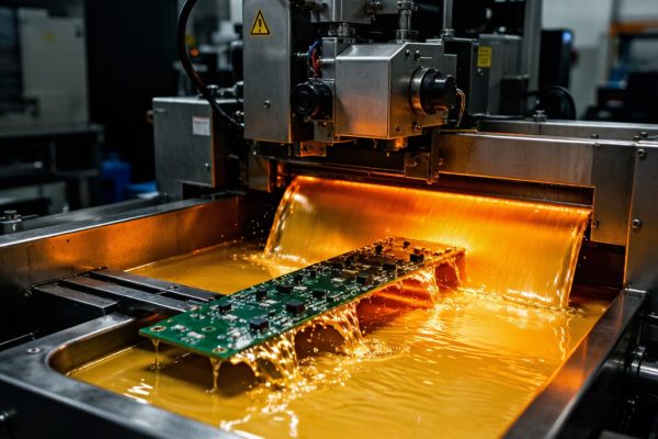
The most widely used underfill type for flip-chip and BGA applications. Low-viscosity (1–10 Pa·s) epoxy resin is dispensed along one or two edges of the die after reflow soldering. Capillary action draws the material into the gap between die and substrate, after which the assembly is heated to cure the epoxy.
Key material properties:
- CTE: 20–40 ppm/°C below Tg, 60–100 ppm/°C above Tg. Lower CTE reduces die stress but requires higher filler loading, which increases viscosity and slows capillary flow.
- Glass transition temperature (Tg): 60–150°C. Higher Tg underfills maintain modulus at elevated operating temperatures but are more brittle at low temperatures.
- Filler content: 50–70 wt% silica (SiO₂) particles. Filler reduces CTE and increases thermal conductivity but raises viscosity. Typical filler particle size is 0.5–5 μm, with sub-micron fillers enabling flow into gaps as small as 10 μm.
- Elastic modulus: 6–12 GPa at room temperature. Higher modulus provides better strain redistribution but increases die warpage stress.
No-Flow Underfill
Applied to the substrate before die placement, no-flow underfill combines flux and underfill functions. The material fluxes the solder during reflow and cures simultaneously with solder joint formation. This eliminates the separate underfill dispense-and-cure step, reducing process time by 30–50%.
The trade-off is narrower process compatibility: no-flow underfill must cure at reflow temperatures without outgassing that would create voids in solder joints, while simultaneously providing adequate flux activity. This dual-function requirement limits the formulation space, and no-flow underfills typically achieve lower reliability improvement (5–20× life extension) compared to capillary underfills.
Molded Underfill
For wafer-level packaging, underfill is applied at the wafer scale before singulation — essentially overmolding the entire die surface with a thin encapsulant layer. This approach provides the highest throughput but requires that all dies on the wafer use identical underfill specifications.
Dispensing Process Optimization
Capillary underfill dispensing appears simple — apply liquid and let it flow — but achieving void-free, complete fill requires careful process control:
Substrate preheating: Preheating the PCB to 60–90°C reduces underfill viscosity, accelerating capillary flow. Flow time is approximately inversely proportional to viscosity, and viscosity typically decreases by 50% per 20°C temperature increase. However, temperatures above 90°C risk initiating cure before flow completes.
Dispense pattern: For square dies up to 15 mm, a single-edge “L” pattern (along two adjacent edges) typically provides complete fill. For larger dies or high-aspect-ratio rectangles, a “U” pattern along three edges may be required. The dispense needle should be positioned 0.1–0.3 mm from the die edge at a 30–45° angle.
Fillet control: After complete underfill flow, a secondary dispense pass along the die perimeter creates the “fillet” — the visible epoxy meniscus at the die edge. The fillet serves both cosmetic and functional purposes: it eliminates stress concentration at the die edge where the underfill-air interface would otherwise terminate, and it provides a visual inspection feature for process quality.
Thermal Cycling Reliability Data
Published reliability studies (IPC-9701 thermal cycling, −40°C to +125°C, 15-minute dwell) for flip-chip assemblies demonstrate the magnitude of underfill benefit:
| Configuration | Characteristic Life (N63.2%) | Failure Mode |
|---|---|---|
| No underfill | 200–500 cycles | Solder joint fatigue crack |
| No-flow underfill | 2,000–5,000 cycles | Mixed: solder + underfill delamination |
| Capillary underfill, Tg=80°C | 5,000–15,000 cycles | Underfill delamination → solder crack |
| Capillary underfill, Tg=135°C | 15,000–30,000 cycles | Solder fatigue (delayed) |
| Capillary underfill + edge bond | 25,000–50,000 cycles | Substrate trace fracture |
The data reveals an important insight: as underfill reliability improves, the failure mode shifts from the solder joint to the underfill-to-die or underfill-to-substrate interface, and eventually to the substrate itself. The “weakest link” in the system migrates as each interface is strengthened.
Inspection and Quality Control
CSAM (C-SAM) inspection: C-mode Sca
ing Acoustic Microscopy is the gold standard for detecting underfill voids and delamination. A 15–30 MHz transducer can resolve voids as small as 50 μm within the underfill layer. Accept/reject criteria typically allow up to 5% void area for commercial applications and <1% for automotive or aerospace reliability grades.
Cross-section analysis: Destructive cross-sectioning through the die corner — the highest-stress location — reveals underfill fillet geometry, void distribution, and filler particle settlement. Filler settling (higher filler concentration near the substrate than near the die) indicates excessive flow time or insufficient filler suspension in the formulation.
Dye-and-pry testing: A quick qualitative check for underfill adhesion. Immerse the assembly in red dye, dry, then mechanically pry the die from the substrate. Red dye on the die underside indicates areas where underfill failed to adhere, while clean underfill fracture surfaces indicate cohesive (good) failure within the epoxy.
Selection Decision Matrix
Choose capillary underfill when reliability is the primary driver — automotive, aerospace, medical, and high-reliability industrial applications where 15,000+ thermal cycles are required. The additional process step and longer cycle time are justified by the 10–100× life improvement.
Choose no-flow underfill for consumer electronics where cost and throughput dominate and the expected product life is 3–5 years with moderate thermal cycling (500–2,000 cycles). The 5–20× life improvement is adequate for these applications.
Skip underfill entirely only when CTE mismatch is minimal (ceramic substrates, CTE-matched laminates), when mechanical constraints prevent die-substrate relative movement (small die, rigid assembly), or when the application experiences fewer than 100 thermal cycles over its intended life.
For Southeast Asian electronics manufacturers producing flip-chip and BGA assemblies for export markets, underfill encapsulation is increasingly a non-negotiable reliability requirement — not because every product needs 30,000-cycle life, but because a single early-life solder joint failure in the field can trigger warranty costs that far exceed the entire underfill process cost for the production run.