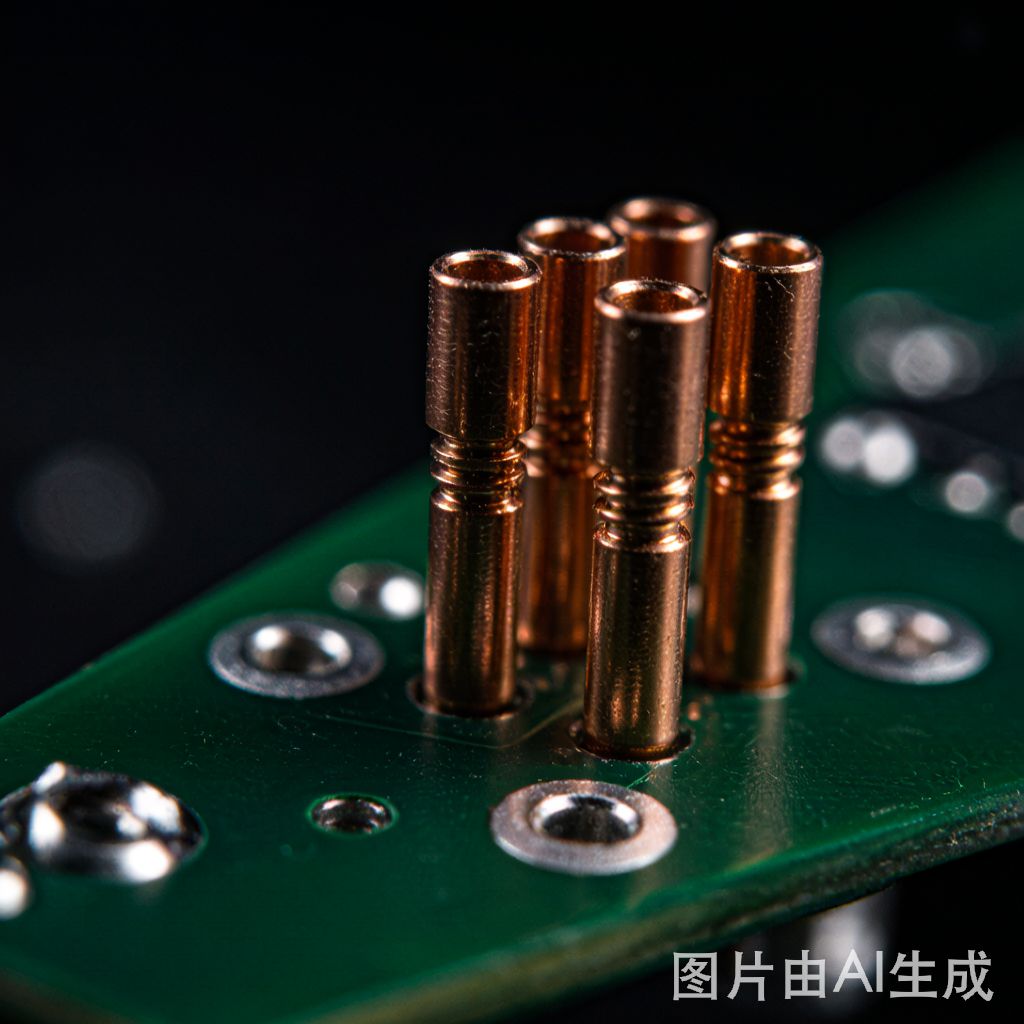
## What Are Copper Press-Fit Pins?
Copper press-fit pins represent a revolutionary interco
ect technology that eliminates the need for soldering in PCB assembly. Instead of relying on molten solder to create electrical and mechanical co
ections, press-fit pins use precisely engineered compliant sections that deform slightly during insertion, creating a gas-tight, high-reliability contact directly with the copper-plated through-hole.
This technology has gained significant traction in automotive, industrial, and telecommunications electronics where zero-solder reliability is paramount. For SMT manufacturers in Southeast Asia, press-fit technology offers a compelling alternative to traditional soldering for power co
ections, backplane interfaces, and high-pin-count co
ectors.
## Compliant Pin Geometry: The Engineering Behind the Co
ection
The core of press-fit technology lies in the compliant section geometry. Two primary designs dominate the industry:
### Eye-of-the-Needle (EON) Design
The EON design features a hollow cylindrical section with a longitudinal slit, creating a spring-like structure. During insertion, the EON section compresses inward, then springs back to press against the hole wall. Key parameters include:
– Outer diameter: Typically 0.85mm for a 0.9mm plated-through-hole (10% oversize)
– Slot width: 0.15-0.25mm, controlling spring force
– Material: Copper alloy C7025 or C19010 (high yield strength with good elasticity)
### Solid Compliant Design
Solid compliant pins use a carefully shaped cross-section (often a square or star shape) that is slightly larger than the target hole. During insertion, the pin material yields locally, creating permanent deformation that maintains contact force:
– Cross-section: Typically 0.95mm square for a 0.9mm hole
– Material: Brass C26000 or copper alloy C19400
– Insertion force: 2-5N per pin depending on geometry
## Insertion Force Control and Process Requirements
Successful press-fit assembly demands precise force control. The insertion process follows a characteristic force curve:
1. Entry phase (0-0.5mm): Pin tip enters the hole, force rises gradually
2. Compliance phase (0.5-2.0mm): Compliant section deforms, peak force reaches 3-8N
3. Settling phase (2.0-3.5mm): Pin seats fully, force drops to retention level
Critical process parameters:
– Press speed: 10-50mm/s (too fast causes pin buckling, too slow creates intermittent contacts)
– Press force monitoring: Each pin insertion must be recorded for traceability
– Hole quality: Plated-through-hole diameter tolerance ±0.05mm, copper plating thickness 25±5μm
– Board support: Bottom-side support prevents PCB flexure during press operations
## Reliability Testing Standards (IEC 60352-5)
Press-fit co
ections must meet rigorous reliability standards defined by IEC 60352-5. The standard specifies comprehensive test sequences:
### Thermal Cycling Reliability
– Test condition: -40°C to +125°C, 1000 cycles
– Pass criteria: Contact resistance change ≤20mΩ, no visual cracks
– Failure mechanism: CTE mismatch between copper pin and FR-4 substrate creates cumulative micro-strain
### Vibration and Mechanical Shock
– Vibration: 10-2000Hz, 0.5mm amplitude, 20g peak
– Shock: 30g, 11ms half-sine pulse
– Pass criteria: No pin withdrawal ≥0.1mm, contact resistance stable
### Current Carrying Capacity
Copper press-fit pins typically carry 2-8A per pin depending on cross-section area. The gas-tight co
ection ensures low contact resistance (typically 1-5mΩ), making press-fit ideal for power distribution rails where solder joints would add parasitic resistance.
## Copper Alloy Selection for Press-Fit Applications
Material selection directly impacts press-fit performance. The alloy must balance yield strength (for compliance), elasticity (for retention force), and conductivity:
| Alloy | Yield Strength | Conductivity | Application |
|——-|—————|————-|————-|
| C7025 (CuNi2Si) | 650 MPa | 40% IACS | EON pins, high-reliability |
| C19010 (CuNi1CoSi) | 600 MPa | 45% IACS | EON pins, automotive |
| C26000 (Brass) | 200 MPa | 27% IACS | Solid compliant, cost-sensitive |
| C19400 (CuFe2) | 340 MPa | 60% IACS | Solid compliant, power pins |
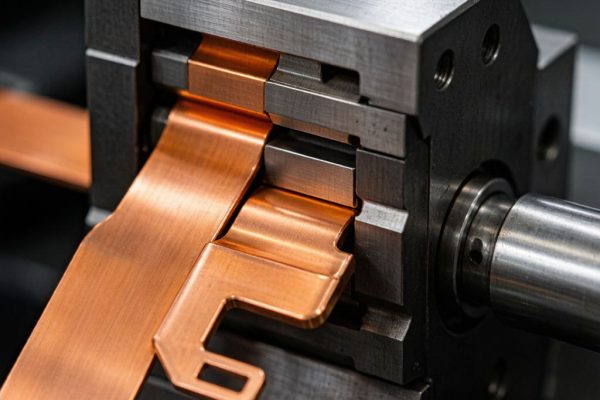
For Southeast Asian SMT manufacturers sourcing from TechMartSE, C7025 and C19010 copper strips provide the optimal balance for press-fit pin stamping, offering high yield strength with sufficient formability for progressive die production.
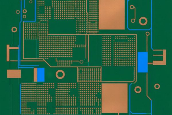
## PCB Design Guidelines for Press-Fit Implementation
Successful press-fit implementation requires specific PCB design rules:
– Hole diameter: Follow manufacturer datasheet (typically 0.9mm ±0.05mm for 0.6mm pins)
– **A
ular ring**: Minimum 0.25mm around plated-through-hole
– Copper plating: Minimum 25μm in hole, smooth surface (no dendrites)
– No solder mask in hole: Mask must not enter the PTH barrel
– Board thickness: Minimum 1.6mm for adequate pin engagement length
– Layer stackup: Avoid internal plane co
ections directly at press-fit holes (use thermal relief pads)
## Advantages Over Traditional Soldering
Press-fit technology offers several compelling advantages for SMT manufacturers:
1. Zero thermal stress: No reflow heat exposure for the co
ection zone
2. No solder defects: Eliminates cold joints, voids, and tombstone issues at the interface
3. Rework simplicity: Pins can be pressed out and replaced without desoldering
4. Environmental benefit: No lead, no flux, no cleaning required
5. Dual-side assembly: Press-fit can be performed after both sides have been reflowed, enabling true double-sided SMT assembly sequences
## Conclusion
Copper press-fit pin technology represents a mature, reliable alternative to soldered interco
ects for SMT electronics manufacturing. By understanding compliant pin geometry, insertion force dynamics, and IEC 60352-5 reliability requirements, manufacturers can leverage this zero-solder approach to achieve higher reliability, lower process complexity, and better environmental compliance in their PCB assemblies. For sourcing high-quality copper alloys suitable for press-fit pin production, TechMartSE offers C7025, C19010, and C19400 strips with certified mechanical properties.