Why Edge Quality Matters in Electronics-Grade Copper Strip
In the copper strip supply chain for electronics manufacturing, edge quality is an overlooked but critical specification. Copper strip is produced in wide coils (200–600 mm) at the mill and then slit to the final width (3–50 mm for most SMT component applications) by a slitting operation at the service center or stamping facility. The slitting process creates burrs—a thin, elongated ridge of displaced metal along the cut edge—that can range from 5 μm to 100+ μm depending on the slitting parameters and tool condition.
For precision stamped components (EMI shielding clips, co
ector contacts, spring contacts, lead frames), burrs affect three critical downstream processes:
- Stamping die life: Burrs on the strip edge accelerate progressive die wear by 30–50%, increasing tool maintenance cost and dimensional variation over the die life cycle.
- Component dimensional accuracy: Burrs add effective material thickness at the strip edge, causing stamped bend angles to deviate from design intent and contact spring forces to vary beyond specification.
- Solder joint quality: Burrs prevent proper seating of stamped components on solder paste deposits, create air gaps under the component that trap flux residues, and can physically displace solder paste onto adjacent pads during placement.
This article covers the mechanics of burr formation, measurement methods, slitting process optimization, and edge treatment processes that ensure electronics-grade copper strip with burr heights below 10 μm—the threshold for reliable SMT assembly.
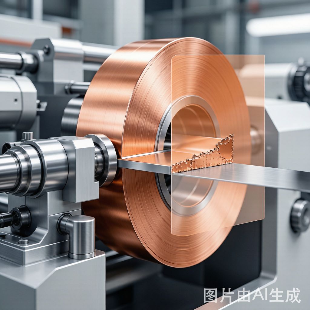
The Mechanics of Burr Formation in Slitting
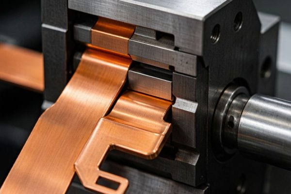
Shear Slitting Process
Copper strip slitting uses rotary shear knives—two opposing circular blades that rotate in opposite directions, shearing the strip like a pair of rotating scissors. The strip passes between the top and bottom knives, which overlap by a small amount (the knife overlap, typically 0.5–2.0 mm) and are set with a horizontal gap (the knife clearance, typically 5–15% of the strip thickness).
The slitting process produces three distinct zones on the cut edge:
- Roll zone (top 20–40% of edge thickness): The material is plastically deformed by the knife pressure, creating a smooth, rounded surface with a slight radius. This is the “good” part of the edge.
- Shear zone (middle 40–60%): The material fractures cleanly along the shear plane, producing a smooth, straight surface that is the most dimensionally accurate portion of the edge.
- Burr zone (bottom 5–20%): As the knives complete the cut, the remaining material at the bottom of the strip tears rather than shears, producing a burr that extends outward from the strip surface. The burr height depends on the knife clearance, overlap, strip thickness, and material hardness.
Burr Height vs. Slitting Parameters
The relationship between slitting parameters and burr height is well-established:
- Knife clearance (gap between top and bottom knives): This is the most influential parameter. Too much clearance (>15% of strip thickness) allows the material to bend before shearing, producing a large burr (30–80 μm for 0.5 mm strip). Too little clearance (<5%) causes the knives to rub rather than shear, generating excessive heat, knife wear, and a secondary burr on the opposite edge. Optimal clearance is 8–12% of strip thickness for copper alloys.
- Knife overlap: Excessive overlap (>2 mm for thin strip) increases the roll zone and burr height. Minimal overlap (0.5–1.0 mm) produces the cleanest cut with the smallest burr, but requires precise knife alignment to avoid miscuts.
- Strip hardness: Harder tempers (half-hard, hard) produce smaller burrs than soft (a
ealed) temper because the harder material fractures more cleanly. A half-hard C2680 brass strip typically produces 30–40% less burr than the same alloy in soft temper under identical slitting conditions.
- Knife condition: Worn knife edges (edge radius >0.05 mm) produce burrs 2–3× larger than fresh knives. Knife wear is accelerated by copper’s tendency to adhere to the knife surface (galling), which rounds the cutting edge over time.
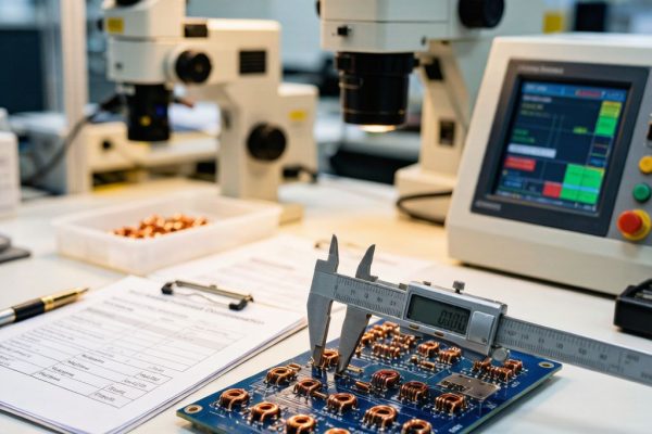
Burr Measurement and Specification
Measurement Methods
Three methods are commonly used to measure burr height on slit copper strip:
- Optical profilometry: A laser or white-light profilometer scans the strip edge and produces a 3D surface map with burr height resolution of 1 μm. This is the most accurate method and can distinguish between the roll zone, shear zone, and burr zone on a single edge profile. Typical cost: $2–5 per measurement at a metrology lab, or in-house with a $15,000–30,000 instrument.
- Feeler gauge method: Place a precision feeler gauge against the strip surface at the burr location and measure the gap between the gauge and the strip surface. Resolution: 5–10 μm. Quick and inexpensive but measures only the maximum burr height, not the full edge profile.
- Microscopy with cross-section: Cut a sample from the slit strip, mount it in epoxy, polish the cross-section, and measure burr height under a metallurgical microscope at 50–200× magnification. Resolution: 1 μm. The most complete measurement (shows burr height, shape, and root thickness) but destructive and time-consuming (30–60 minutes per sample).
Specification Levels for Electronics Applications
| Application | Max Burr Height | Edge Quality Level | Typical Specification |
|---|---|---|---|
| EMI shielding clips, spring contacts | ≤10 μm | Premium | Deburred + rolled edge |
| Co
ector contacts, lead frames |
≤20 μm | Standard | Slit with optimized parameters |
| Bus bars, thermal strips | ≤50 μm | Commercial | Standard slit, no deburring |
For SMT component stamping, the ≤10 μm specification (Premium grade) is recommended for any component that contacts solder paste or fits into a tight stamping die clearance. The ≤20 μm (Standard) grade is acceptable for components that are mechanically assembled (screw terminals, co
ector shells) where the burr is removed by subsequent machining operations.
Slitting Process Optimization for Minimum Burr
Knife Selection and Setup
- Knife material: Use D2 tool steel knives for standard production (good wear resistance, cost-effective at $50–100 per knife). For high-volume continuous slitting (>50,000 m per knife set), use tungsten carbide knives (10× longer wear life, $200–400 per knife, but vulnerable to chipping on strip weld joints).
- Knife diameter: Larger diameter knives (200–250 mm) produce smaller burrs than small knives (100–150 mm) because the larger circumference provides a more gradual shear angle. The larger knife also has more cutting edges available before requiring regrinding.
- Knife clearance setting: Set the horizontal clearance between top and bottom knives to 8–12% of strip thickness. For 0.5 mm strip, this means 40–60 μm clearance. Measure clearance with a feeler gauge or optical comparator at three points across the knife width (left, center, right) to ensure uniformity within ±5 μm.
- Knife overlap: Set overlap to 0.5–1.0 mm for strip thickness ≤1.0 mm, and 1.0–2.0 mm for thickness >1.0 mm. Excessive overlap increases burr; insufficient overlap causes incomplete cuts and ragged edges.
Line Speed and Tension Control
The strip speed through the slitter affects burr formation through two mechanisms:
- Speed effect on shear: At higher speeds (≥100 m/min), the material shears more cleanly because the strain rate is higher, promoting fracture over plastic deformation. However, high speed also increases knife wear rate and generates more heat at the knife edge, which can soften the copper and increase galling.
- Tension effect: Strip tension across the slitter must be uniform and controlled. Uneven tension causes the strip to oscillate vertically between the knives, producing alternating thick-thin burr patterns along the edge. Use a closed-loop tension control system (dancer roll or load cell feedback) to maintain ±5% tension uniformity.
Recommended operating parameters: line speed 50–80 m/min for electronics-grade strip, with tension set to 10–20% of the strip’s yield force (e.g., 50–100 N for 0.5 mm × 20 mm C2680 half-hard strip).
Knife Maintenance Schedule
- Regrind interval: D2 steel knives every 5,000–10,000 m of slit length. Tungsten carbide every 30,000–50,000 m. The regrind restores the cutting edge radius to <0.02 mm and removes any galling buildup.
- Knife replacement: After 4–6 regrinds (D2) or 2–3 regrinds (carbide), the knife diameter has reduced to the minimum usable size and must be replaced.
- Burr monitoring: Measure burr height at the start of each coil and every 2,000 m during production. If burr height exceeds the specification limit, stop the line and regrind or replace the knives before continuing.
Edge Treatment Processes for Electronics-Grade Strip
1. Roller Deburring
After slitting, the strip passes through a roller deburring station that compresses the burr back into the strip edge using hardened steel rollers. This process reduces burr height by 60–80% (e.g., 40 μm → 8–16 μm) without changing the strip width dimension. Roller deburring is the most cost-effective edge treatment for electronics-grade strip because it is integrated into the slitting line and adds no separate processing step.
2. Brush Deburring
A rotary wire brush station removes burrs by mechanical abrasion. Brush deburring achieves <5 μm residual burr height but can round the strip edge and remove 5–15 μm of material from the strip width. This width reduction must be accounted for in the stamping die design. Brush deburring is preferred for the tightest burr specifications (≤10 μm) on strip thicker than 0.3 mm (thin foil may be damaged by brush abrasion).
3. Chemical Etch Deburring
For very thin strip (<0.2 mm) where mechanical deburring risks damaging the material, a chemical etch process dissolves the burr by immersing the slit strip in a mild acid solution (dilute H₂SO₄ or FeCl₃) for 10–30 seconds. The etch preferentially removes the thin burr because its small cross-section dissolves faster than the strip body. Chemical etch produces burr-free edges (<1 μm) but requires wastewater treatment and adds 5–10 μm of width reduction from etching the strip edge surface.
4. Precision Slitting with Double-Knife Configuration
A double-knife (quad slitter) configuration uses two top knives and two bottom knives per slit position, cutting from both sides of the strip simultaneously. This produces balanced burrs on both edges that are approximately 50% smaller than single-knife burrs because the shear force is distributed symmetrically. Double-knife slitting is the preferred method for premium-grade strip (≤10 μm burr) when the strip width is wide enough (≥10 mm) to accommodate the knife spacing.
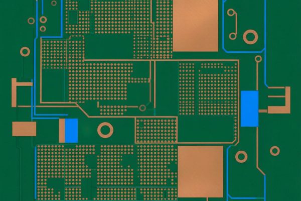
Impact of Burr on Downstream SMT Processes
Stamping Die Life
Burrs on the strip entering a progressive stamping die act as abrasive micro-edges that wear the die clearance surfaces. A 30 μm burr on 0.5 mm strip increases the effective strip thickness by 6% at the burr location, forcing the die to accommodate this extra material. Over 50,000 strokes, burr-induced die wear increases punch-to-die clearance by 10–20 μm, causing part dimensional drift and eventually requiring die refurbishment.
With ≤10 μm burr strip, die life extends by 30–50% compared to standard (≤50 μm) burr strip because the reduced edge irregularity minimizes abrasive contact in the die clearance zone.
Solder Paste Contact
A stamped component with 20 μm burrs on its contact edges sits on solder paste with an air gap created by the burr ridge. The air gap prevents full wetting of the component contact surface, reduces the effective solder joint area by 10–20%, and traps flux volatiles that create voids in the reflowed joint. IPC-A-610 limits voiding to 25% of the joint area for Class 2 and 10% for Class 3—burrs on component contact surfaces can push voiding beyond these limits.
With ≤10 μm burr components, the contact surface sits flush on the solder paste, achieving full wetting and minimal voiding without any special process adjustments.
Conclusion
Copper strip edge quality and burr control are foundational to SMT component quality—yet they are rarely specified explicitly in procurement documents. The default slitting process at most service centers produces 30–50 μm burrs, which are acceptable for bus bars and thermal strips but problematic for precision stamped components that contact solder paste or fit into tight stamping die clearances. For electronics-grade applications, specify ≤10 μm maximum burr height and require roller deburring or brush deburring as part of the slitting process. The cost difference between standard slit (≤50 μm) and premium slit (≤10 μm) copper strip is typically 5–10%—a minor premium that pays for itself in extended die life, improved dimensional consistency, and reduced solder joint voiding across the entire downstream process chain.