The Tin Whisker Problem in Lead-Free Electronics
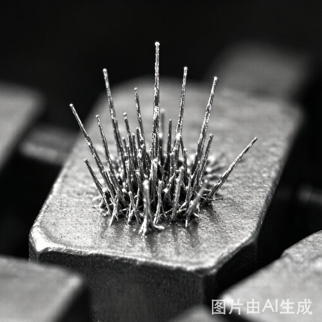
When the electronics industry transitioned from SnPb to lead-free finishes under the RoHS directive, it solved one problem and inherited another. Pure tin and high-tin alloy finishes (Sn, SnCu, SnBi) are susceptible to a metallurgical phenomenon called tin whisker growth—spontaneous, single-crystal filaments that grow from plated surfaces and can reach lengths of several millimeters. These conductive filaments pose a critical reliability risk: a single tin whisker bridging adjacent fine-pitch pads can cause a dead short, triggering system failure in anything from pacemakers to satellite power supplies.
This guide covers the science behind tin whisker formation, industry-standard testing methodologies, and practical mitigation strategies for SMT assemblies in high-reliability applications.
What Causes Tin Whiskers to Grow?
Tin whiskers grow from compressive stress within the tin plating layer. This stress originates from several sources:
- Residual plating stress: Bright tin electroplating deposits produce fine-grain structures with high internal stress due to co-deposited organic brighteners and carbon impurities.
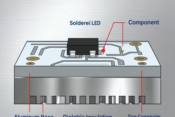
- Intermetallic compound (IMC) formation: Cu₆Sn₅ IMC grows at the tin-copper interface over time. The volume expansion associated with IMC growth creates compressive stress that drives whisker extrusion.
- CTE mismatch: Tin (CTE ~23 ppm/°C) expands faster than copper (CTE ~17 ppm/°C) or the substrate. Thermal cycling generates cyclic compressive stress in the tin layer.
- External mechanical stress: Bending, torque on fasteners, or co
ector insertion forces can induce localized compressive zones that nucleate whisker growth.
Whiskers typically grow 0.1–2.0 mm in length with diameters of 1–5 μm, though outliers exceeding 10 mm have been documented. The incubation period ranges from days to years, making this a particularly challenging failure mode to screen during manufacturing.
Industry Standards for Tin Whisker Testing
JEDEC JESD22-A121 (JP002)
JEDEC JP002 is the most widely adopted tin whisker test standard. It defines three test conditions designed to accelerate whisker growth:
- Temperature cycling: -55°C to +85°C, air-to-air, with a 10–15 minute dwell. Inspect at 500, 1,000, and 1,500 cycles.
- Ambient temperature/humidity storage: 30°C / 60% RH for 4,000 hours, with inspections at 1,000-hour intervals.
- High temperature/humidity storage: 55°C / 85% RH for 4,000 hours, with inspections at 1,000-hour intervals.
Acceptance criteria are based on maximum whisker length: Class 1 (consumer) allows up to 67 μm, Class 2 (industrial/enterprise) allows up to 50 μm, and Class 3 (high-reliability/aerospace) typically requires zero whiskers exceeding 40 μm.
iNEMI Risk Assessment Framework
The International Electronics Manufacturing Initiative (iNEMI) published a risk-based approach that evaluates three factors: plating chemistry risk (matte tin being lowest risk, bright tin highest), application environment severity, and consequence of failure. Their recommendation matrix guides whether mitigation is required—for example, a bright-tin-finished QFP in a high-humidity environment with a safety-critical function would mandate full mitigation.
Effective Mitigation Strategies
1. Matte Tin Plating Over Bright Tin
Matte tin finishes have grain sizes of 1–5 μm versus 0.1–0.5 μm for bright tin. The larger grain structure accommodates compressive stress through grain boundary sliding rather than localized whisker extrusion. Matte tin consistently exhibits whisker densities 10–100× lower than bright tin in JEDEC testing.
2. Nickel Underlayer Barrier
Electroplating a 1.5–2.5 μm nickel layer between the copper substrate and tin finish creates a diffusion barrier that prevents Cu₆Sn₅ IMC formation. Without IMC growth, one of the primary compressive stress sources is eliminated. Ni/Au with a flash gold layer on top provides additional oxidation resistance while maintaining whisker suppression.
3. Post-Plate A
ealing
Baking plated components at 150°C for 1 hour (as specified in MIL-STD-883) relieves residual plating stress through recrystallization. This a
eal step reduces internal stress by 40–60% and is mandatory for many defense and aerospace specifications.
4. Conformal Coating
Conformal coating (acrylic, silicone, urethane, or parylene) forms a physical barrier that contains whiskers. Even if whiskers grow beneath the coating, they ca
ot penetrate through to cause shorts. Testing has demonstrated that 25 μm of acrylic conformal coating effectively prevents whisker-induced shorts in fine-pitch applications. Parylene C at 12.5–25 μm provides the best coverage on complex 3D geometries.
5. Alloying Additions
Adding 1–2% bismuth or 0.5–2.0% silver to the tin plating bath alters the grain structure and IMC formation kinetics, reducing whisker propensity. However, alloy plating requires tighter process control and is less common than pure matte tin.
Practical Guidance for SMT Manufacturers
For most commercial and industrial SMT assemblies, a three-layer defense is recommended: specify matte tin finishes on component leads, apply a nickel underlayer on any custom copper components, and use conformal coating when the application involves high humidity, vibration, or safety-critical functions. For space and defense applications, post-plate a
ealing and rigorous JEDEC JP002 qualification are non-negotiable.
Conclusion
Tin whiskers are a manageable risk, not an unsolvable problem. By combining matte tin plating, nickel barrier layers, post-plate a
ealing, and conformal coating where needed, SMT manufacturers can achieve the reliability levels required by even the most demanding applications. The key is matching the mitigation strategy to the risk profile—over-engineering is expensive, but under-engineering can be catastrophic.