The CTE Mismatch Problem in SMT Design
One of the most persistent reliability challenges in Surface Mount Technology (SMT) is the coefficient of thermal expansion (CTE) mismatch between different materials in an assembly. When components with different CTEs are bonded together — such as silicon dies mounted on copper heat spreaders, or ceramic capacitors soldered to FR-4 PCBs — thermal cycling creates mechanical stress at the interfaces. Over time, this stress causes solder joint fatigue, delamination, and ultimately, product failure.
The numbers tell the story: silicon has a CTE of approximately 2.6 ppm/°C, while copper’s CTE is about 17 ppm/°C. FR-4 PCBs typically exhibit CTE values of 14-18 ppm/°C in the X-Y plane, but can reach 50-70 ppm/°C in the Z-axis. These mismatches create significant stress during thermal cycling, particularly in high-power applications where temperature swings of 50-100°C are common.
Copper-Invar-Copper (CIC) laminate has emerged as an elegant solution to this problem, offering a tunable CTE that bridges the gap between low-expansion materials and standard electronics substrates.
What Is Copper-Invar-Copper Laminate?
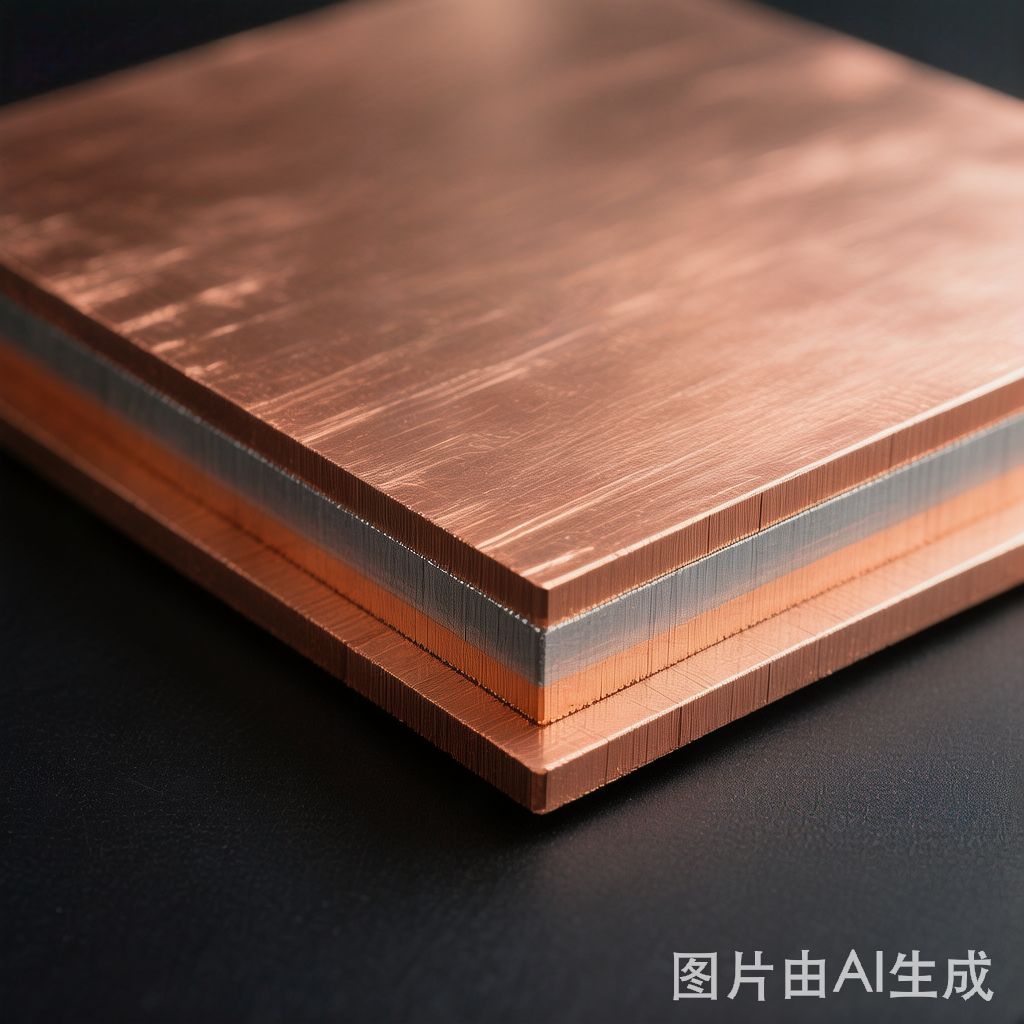
CIC laminate is a three-layer composite material consisting of an Invar (FeNi36) core sandwiched between two copper outer layers. The construction leverages the dramatically different CTEs of its constituent materials:
- Copper outer layers: CTE ≈ 17 ppm/°C. Provide excellent electrical and thermal conductivity.
- Invar core: CTE ≈ 1.2 ppm/°C. An iron-nickel alloy with exceptionally low thermal expansion, used in precision instruments for over a century.
The resulting composite CTE depends on the relative thickness of each layer. A typical CIC laminate with 20% copper / 60% Invar / 20% copper by thickness achieves a composite CTE of approximately 5-6 ppm/°C — remarkably close to that of semiconductor materials like silicon and gallium arsenide.
Manufacturing CIC Laminate
CIC laminate is produced through several manufacturing processes:
Roll Bonding
The most common method, where copper and Invar strips are passed through high-pressure rollers to create a metallurgical bond. This process can produce CIC strip in continuous coils, making it suitable for high-volume production. Roll-bonded CIC typically uses copper layers of 0.05-0.15 mm on each side of a 0.15-0.5 mm Invar core.
Explosive Bonding
For thicker CIC plates used in power electronics, explosive bonding creates an exceptionally strong bond between the copper and Invar layers. This method produces thicker laminates (2-10 mm total) suitable for high-power bus bars and heat sinks.
Electroplating
For precision applications, copper can be electroplated onto an Invar substrate, allowing very precise control of the copper layer thickness. This method is used for thin CIC foils in RF and microwave applications.
Key Properties and Advantages
Tunable CTE
The most valuable property of CIC laminate is its ability to match the CTE of virtually any material in the electronics assembly. By adjusting the copper-to-Invar thickness ratio, the composite CTE can be engineered to fall anywhere between 1.2 and 17 ppm/°C:
- 10% Cu / 80% Invar / 10% Cu → CTE ≈ 3 ppm/°C (matches silicon)
- 20% Cu / 60% Invar / 20% Cu → CTE ≈ 5-6 ppm/°C (matches GaAs, ceramic)
- 30% Cu / 40% Invar / 30% Cu → CTE ≈ 8-10 ppm/°C (bridges ceramic and FR-4)
Electrical Conductivity
While the Invar core is a relatively poor conductor, the copper outer layers provide adequate electrical conductivity for most SMT applications. The surface resistivity of CIC is dominated by the copper layers, making it suitable for RF ground planes and EMI shielding applications. Typical surface resistivity is approximately 30-50% of pure copper, depending on the copper fraction.
Thermal Conductivity
CIC’s thermal conductivity (approximately 150-200 W/m·K for typical constructions) is lower than pure copper (385 W/m·K) but significantly higher than Invar alone (10-15 W/m·K). This makes CIC an effective thermal management material in applications where CTE matching is also required.
Applications in SMT Electronics
Power Module Substrates
In IGBT and MOSFET power modules, CIC substrates replace pure copper to eliminate CTE mismatch with the silicon dies. This dramatically improves thermal cycling reliability — typically extending module life from 10,000 to 30,000+ cycles. The copper outer layers maintain solderability for die attach and lead frame co
ections.
RF and Microwave Circuits
For high-frequency circuits operating at 10-40 GHz, CIC laminates serve as constraint layers in PCB constructions. By matching the CTE of the RF substrate material, CIC prevents delamination and via cracking during thermal cycling — a critical reliability concern for aerospace and satellite applications.
LED Packaging
High-power LED packages use CIC submounts to match the CTE of the GaN-based LED die while providing efficient thermal conduction. This reduces thermal stress on the die attach solder, which is the most common failure point in high-power LED packages.
Hermetic Package Bases
CIC is used as the base material in hermetic electronic packages where the lid, base, and feedthroughs must maintain seal integrity over wide temperature ranges. The matched CTE between the CIC base and the ceramic or glass feedthroughs prevents seal failure during thermal cycling.
Design Considerations
When specifying CIC laminate for SMT applications, engineers should consider:
- Machinability: The difference in hardness between copper and Invar can cause tool wear and burr formation during punching and drilling. Carbide tools with optimized geometries are recommended.
- Plating compatibility: CIC surfaces accept standard tin, nickel, and gold plating processes, but the Invar core requires activation steps for reliable adhesion.
- Bending and forming: CIC can be formed, but the Invar core has limited ductility. Minimum bend radii of 3-5 times the total thickness are recommended to avoid delamination at the copper-Invar interface.
- Cost: CIC laminate costs 3-5 times more than pure copper strip, but the total system cost savings from improved reliability and reduced field failures typically justify the investment in high-reliability applications.
Conclusion
Copper-Invar-Copper laminate represents a sophisticated materials engineering solution to one of SMT design’s most fundamental challenges. By combining the low CTE of Invar with the electrical and thermal conductivity of copper, CIC enables reliable assemblies that would be impractical with conventional materials alone. As electronics continue to push toward higher power densities, higher frequencies, and more demanding thermal environments, CIC laminate will play an increasingly important role in ensuring product reliability across the semiconductor, power electronics, and RF industries.


