## Introduction
High-brightness LED modules, from street lighting to horticultural fixtures and automotive headlamps, push junction temperatures close to their rated limits. Because LEDs convert only a fraction of input power to light, the remainder becomes heat that must be conducted away from the die. Metal-core printed circuit boards (MCPCBs) were developed specifically to solve this problem by replacing the FR-4 substrate with a thermally conductive metal base.
The two dominant metal-core options are aluminum-backed PCBs and copper-core MCPCBs. Both improve heat spreading compared with standard FR-4, but they differ significantly in thermal conductivity, coefficient of thermal expansion (CTE), weight, cost, and solder joint reliability. This article compares the two materials to help engineers select the right substrate for LED heat dissipation.
## How MCPCBs Improve LED Heat Dissipation
### Thermal Stackup
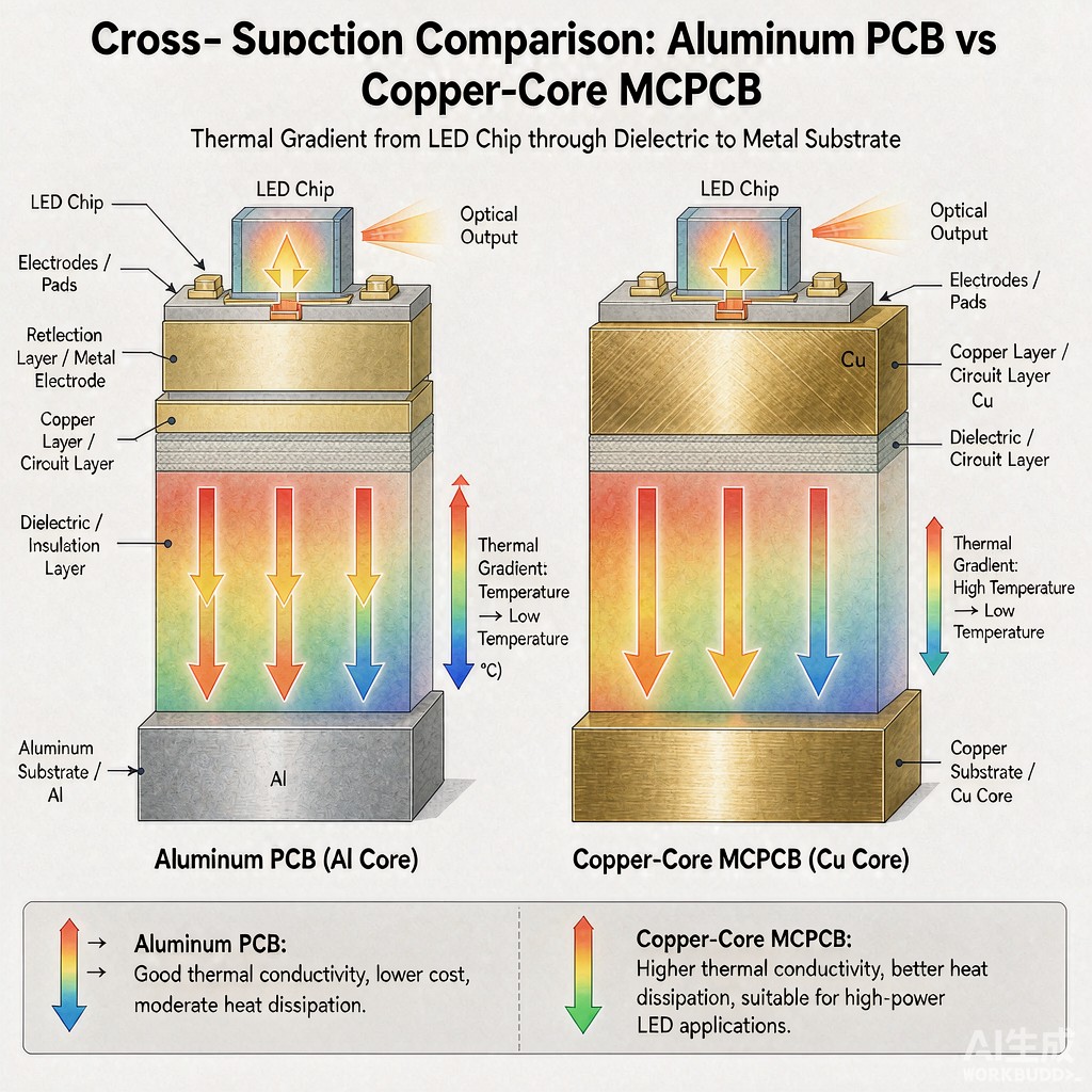
A metal-core PCB consists of three layers: a thin copper circuit layer on top, a thermally conductive dielectric in the middle, and a thick metal base plate on the bottom. Heat generated by the LED package flows vertically through the solder joint, copper trace, dielectric, and into the metal base, where it spreads laterally and dissipates to a heatsink or ambient air.
The dielectric layer is the bottleneck. Standard FR-4 has a thermal conductivity of only 0.3 W/m·K, while ceramic-filled MCPCB dielectrics range from 1.0 to 3.0 W/m·K. High-performance dielectrics can reach 8 W/m·K or more, but they cost significantly more and have reduced electrical isolation.
### Aluminum-Backed PCB Characteristics
Aluminum is the most common MCPCB base material because it is lightweight, inexpensive, and provides good thermal conductivity at roughly 150–200 W/m·K. Aluminum-backed PCBs are widely used in consumer LED lighting, display backlights, and medium-power industrial lighting.
The CTE of aluminum is approximately 23 ppm/°C, which is much higher than silicon-based LED dies and ceramic packages. This mismatch creates shear stress at the solder interface during thermal cycling, particularly for large COB LED arrays. Aluminum also ca
ot be punched or formed into complex shapes as easily as copper, and it requires care in screw-mounting to avoid galling.
### Copper-Core MCPCB Characteristics
Copper-core MCPCBs use a copper base plate with thermal conductivity near 400 W/m·K, more than double that of aluminum. Copper also has a CTE of roughly 17 ppm/°C, closer to common LED package substrates, which improves thermal cycling reliability. Additionally, copper can be electroplated and soldered directly, making it easier to attach side-mount brackets or wire bonds in hybrid assemblies.
The disadvantages are cost and weight. Copper is roughly three times denser than aluminum and significantly more expensive per kilogram, so copper-core boards are usually reserved for high-power density applications such as UV-LED curing systems, laser diodes, and automotive lighting where reliability is critical.
## Design and SMT Assembly Considerations
### Dielectric Selection
For aluminum PCBs used in outdoor LED fixtures, a dielectric with high thermal conductivity and good moisture resistance is essential. Breakdown voltage should exceed 3 kV for safety agency approvals. For copper-core boards in high-reliability applications, ceramic-filled dielectrics with high glass transition temperature help prevent delamination during lead-free reflow at 260 °C peak.
### Reflow Profile
The thick metal base acts as a heat sink during reflow, which can lead to cold solder joints if the profile is not adjusted. Preheat ramp rates should be slower than on FR-4 boards, and peak temperature may need to be 5–10 °C higher to ensure all pads reach liquidus. For double-sided assemblies, adhesive or selective reflow processes are often required.
### Reliability Under Thermal Cycling
Thermal cycling reliability is where copper-core MCPCBs show their greatest advantage. The CTE mismatch between a ceramic LED package and an aluminum base produces shear strain in the solder joint with every on-off cycle. Over a 10,000-hour outdoor lighting lifetime, this shear can lead to solder fatigue and increased thermal resistance. Copper-core boards reduce the CTE mismatch and therefore extend solder joint life, which is why automotive and street-lighting OEMs often specify copper despite the higher material cost.
For aluminum-backed boards, designers sometimes add a thin, compliant thermal interface material between the LED package and the PCB to absorb CTE mismatch. This adds cost and assembly complexity but can deliver acceptable reliability for moderate-power indoor applications.
## Cost Modeling and Procurement
When comparing aluminum and copper MCPCBs, the substrate material is only one line item. Copper-core boards may cost 2–3 times as much as aluminum boards in raw material, but the total system cost can be lower if the design eliminates a separate heatsink, reduces LED junction temperature, or extends warranty life. Procurement teams should evaluate total cost of ownership, including assembly yield, thermal test time, field failure rate, and warranty reserves, rather than comparing unit PCB price alone.
## Conclusion
Aluminum-backed PCBs offer the best cost-to-thermal-performance ratio for most LED lighting products. Copper-core MCPCBs are the better choice when maximum heat dissipation, thermal cycling reliability, and electrical grounding integrity are required. The final selection should be based on LED power density, operating environment, lifetime target, and total system cost rather than substrate price alone.



