The Critical Role of Thermal Interface Materials in Modern Electronics
As semiconductor packages continue to deliver higher performance in ever-smaller footprints, managing heat dissipation at the printed circuit board (PCB) level has become one of the most challenging aspects of thermal design. Even with optimized copper pour areas, thermal vias, and heatsinks, the interface between a hot component package and its cooling solution often represents the largest thermal resistance in the entire heat-flow path. This is where thermal interface materials (TIMs) become indispensable. By filling microscopic air gaps and surface irregularities between mating surfaces, TIMs dramatically reduce contact thermal resistance and enable efficient heat transfer from source to sink.
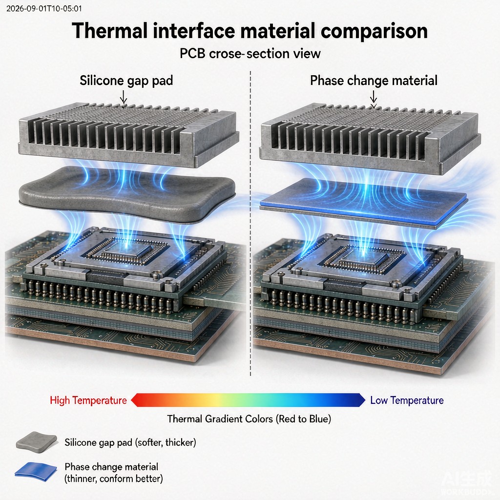
Among the dozens of TIM formulations available to design engineers today, two categories dominate the SMT and PCB assembly landscape: silicone-based thermal gap filler pads and phase change materials (PCMs). Each offers distinct advantages and trade-offs in terms of thermal performance, mechanical compliance, electrical isolation, reworkability, and total cost of ownership. This article provides a comprehensive technical comparison to guide selection decisions for PCB-level thermal management applications.
Silicone Thermal Gap Pads: Structure and Properties
Silicone thermal gap pads are soft, conformable elastomeric sheets formulated from silicone rubber loaded with thermally conductive ceramic fillers such as aluminum oxide (Al₂O₃), boron nitride (BN), or aluminum nitride (AlN). They are supplied in a range of thicknesses—typically 0.5 mm to 5.0 mm—and hardnesses from ultra-soft (Shore OO 20–30) to firm (Shore A 40–60). The silicone matrix provides excellent electrical isolation (dielectric strength 5–20 kV/mm), while the ceramic filler network creates pathways for heat conduction through the material bulk.
Thermal conductivity values for commercially available silicone gap pads span approximately 1.0–12.0 W/m·K, with premium formulations using oriented boron nitride or hybrid fillers reaching the upper end of this range. It is important to recognize, however, that bulk thermal conductivity is only part of the story. The total thermal resistance of a gap pad assembly includes bulk resistance (proportional to thickness and inversely proportional to conductivity) and contact resistances at both interfaces. Ultra-soft, low-modulus pads minimize contact resistance by conforming aggressively to surface topography, often delivering lower total thermal resistance than a higher-conductivity but stiffer pad in real-world assemblies with non-ideal flatness.
Phase Change Materials: How They Work
Phase change materials take a fundamentally different approach to interface thermal management. At room temperature, PCMs are solid sheets or films with a defined shape and thickness—typically 0.1–0.5 mm. When the assembly reaches a characteristic phase-change temperature (usually 45–65 °C), the material softens and flows under light pressure to wet the mating surfaces completely, achieving intimate thermal contact comparable to a liquid TIM but without the pump-out or migration issues associated with thermal greases.
Upon cooling, the PCM resolidifies, maintaining its position and thermal performance indefinitely. This solid-to-liquid-to-solid transition is repeatable across many thermal cycles, making PCMs suitable for applications with fluctuating operating temperatures. The bulk thermal conductivity of PCMs ranges from approximately 0.5–5.0 W/m·K—lower than the best silicone gap pads—but because PCMs achieve exceptionally low contact resistance after phase change, their total thermal resistance in properly assembled joints can equal or even surpass that of thicker gap pads.
Head-to-Head Comparison for PCB Applications
Thermal Performance
In applications where the gap between component and heatsink is small (1.0 mm), caused by component height variations across a PCB or by the need to electrically isolate a heatsink from the board, silicone gap pads are the only practical choice—their thickness and compressibility accommodate non-uniform standoffs while maintaining thermal and electrical isolation.
Mechanical Compliance and Stress
Large-area components such as BGA packages, power modules, and LED arrays can be damaged by excessive mechanical loading during heatsink attachment. Silicone gap pads distribute pressure uniformly and cushion against shock and vibration, making them well-suited for ruggedized or automotive applications. PCMs exert minimal pressure once phase-changed but require sufficient clamping force during the initial softening phase to ensure complete flow and wetting. Designs using PCMs must carefully control heatsink mounting torque and standoff height to avoid excessive stress on delicate SMT packages.
Electrical Isolation
When a metal heatsink is mounted directly over active circuitry, electrical isolation between the heatsink and component terminals is non-negotiable. Silicone gap pads inherently provide excellent dielectric isolation and are available with UL 94 V-0 flammability ratings for safety-critical applications. Standard PCMs based on paraffin or polymer wax blends are also electrically insulating, but their thi
ess means that any pinhole, scratch, or flow-around defect can create a short-circuit risk. Reinforced PCM formulations with fiberglass or polymer mesh supports mitigate this concern but add cost and slightly increase thermal resistance.
Assembly Process and Rework
Silicone gap pads are straightforward to handle and install: peel the release liner, position the pad, and attach the heatsink. They can be pre-cut to complex shapes using die-cutting or laser cutting, and they remain position-stable during handling and shipping. Rework is equally simple—remove the heatsink, replace the pad if it has taken a set, and reassemble.
PCMs require more process discipline. The solid sheet must be precisely positioned before heating; if it shifts during reflow or initial power-up, the thermal interface may be compromised. Some PCMs are supplied with pressure-sensitive adhesive on one side to prevent movement. During rework, the PCM must be fully removed and replaced with fresh material, as the phase-change history alters its flow characteristics and thermal performance. For high-volume manufacturing, this rework cost must be factored into the total cost analysis.
Long-Term Reliability
Both material classes exhibit excellent long-term stability when properly specified. Silicone gap pads can outgas siloxane volatiles in vacuum or hermetic environments, which may be problematic for optical or MEMS devices; low-outgassing formulations (ASTM E595 compliant) are available for such applications. PCMs can experience slight thermal degradation or oxidation if operated continuously near their upper temperature limit, but this is rarely a concern in typical PCB applications where junction temperatures are managed well below 125 °C.
Selection Decision Tree for PCB Designers
Use the following guidelines to narrow the TIM selection for your specific PCB thermal management challenge:
- Small, uniform gap (<0.5 mm): PCM preferred for lowest thermal resistance.
- Large or variable gap (>0.5 mm): Silicone gap pad required for compliance and isolation.
- High-voltage isolation required (>500 V): Thick silicone gap pad (≥1.0 mm) with verified dielectric strength.
- Shock/vibration environment: Silicone gap pad for mechanical damping.
- Frequent rework or prototype builds: Silicone gap pad for ease of handling and replacement.
- Highest thermal performance in thin-gap application: Premium PCM with reinforcement mesh.
Conclusion
Neither silicone thermal gap pads nor phase change materials represent a universal solution for PCB heat dissipation. Each excels in specific application contexts defined by gap geometry, thermal budget, electrical isolation requirements, and manufacturing constraints. By understanding the fundamental differences in thermal conductivity, contact resistance, mechanical compliance, and process compatibility, PCB designers can select the optimal TIM for their thermal management strategy. In many complex assemblies, a hybrid approach—using PCMs for primary heat sources with small gaps and silicone gap pads for secondary components or isolation barriers—delivers the best balance of performance, reliability, and cost.



